Table of Contents
ABLIC's Hall Effect ICs for General UseAutomotive Hall Effect ICs
What is Hall effect IC
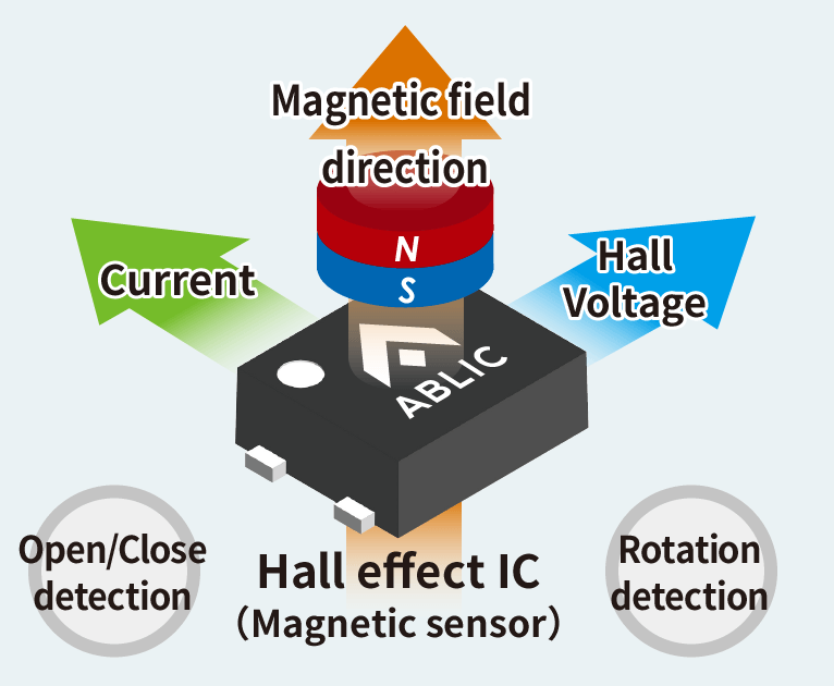
Hall elements are a representative example among various types of magnetic sensors that use semiconductors. Hall elements are sensors that use the galvanomagnetic effect called the Hall effect. Very little voltage can be obtained from a Hall element, so such elements generally require amplifiers such as operational amplifiers. Because a Hall effect IC combines a Hall element and operational amplifier, the number of externally attached components can be reduced and circuit design can be simplified.
It is possible to distinguish the magnetic poles with a single Hall effect IC. Such ICs are used for a wide range of purposes, including general and automotive use. The main detection purposes of Hall effect ICs include rotation detection, position detection, open/closed detection, current detection, direction detection, and various others. General-purpose Hall effect ICs are used for a wide range of products, from large home appliances such as washing machines and refrigerators to mobile phones. Automotive-purpose ICs are naturally used to detect whether windows and doors are open or closed, but many Hall effect ICs are also used for purposes such as detecting vehicle height, speed, and the number of motor rotations.
Principles of Hall effect IC operation
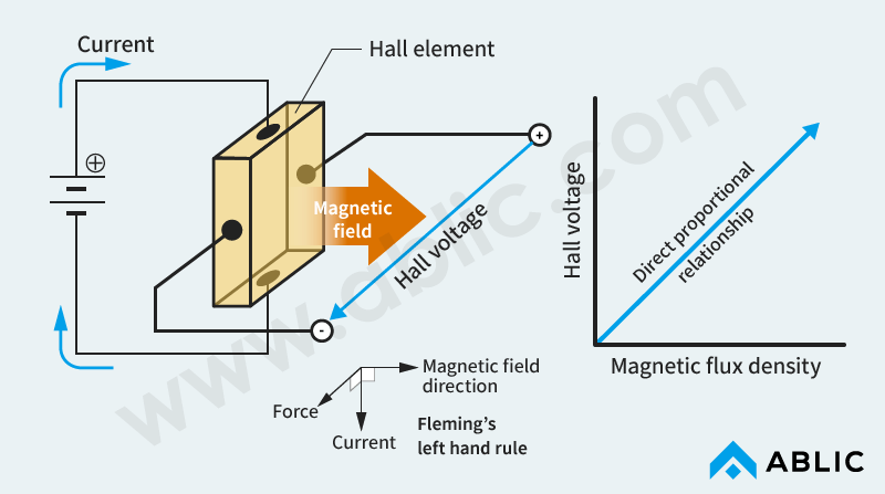
A Hall effect IC incorporates a Hall element. Current flows through this element, and, when a magnetic field (from a magnet) that is perpendicular to the direction of current flow is brought near the element, the carrier which leads the current is affected by a Lorentz force. The Lorentz force results in the generation of voltage (Hall voltage) in the direction perpendicular to the current and magnetic field (the Hall effect). The Hall effect IC detects the existence of the magnetic field (from the magnet) by detecting this voltage. The output voltage increases in direct proportion to the magnetic flux density.
Based on Fleming's left hand rule, the direction of the perpendicular voltage (Hall voltage) changes depending on the direction of the magnetic field (north or south pole). Therefore, a Hall effect IC can detect not only the existence of the magnetic field but also the direction of the field (north or south pole) based on the direction of this voltage.
Hall effect IC Configuration
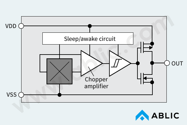
A Hall switch IC amplifies the voltage (Hall voltage) output by a Hall element and outputs a signal by processing the signals inside the IC depending on the magnetic flux density.
There are two types of Hall effect ICs. One is a high-speed operation type for rotation detection of motors etc., and the other is a low current consumption type for battery operated equipment.
Below, Table 1 and Figure 2 show an internal configuration of a low current consumption type Hall effect IC.
| Block | Description |
|---|---|
| Hall element | This detects a magnetic field (from a magnet) and outputs a voltage (Hall voltage). |
| Chopper amplifier | This amplifies the voltage (Hall voltage) output by the Hall element. |
| Sleep/Awake circuit | This controls the operation and non-operation by exercising intermittent control. |
| Comparator with hysteresis (comparison circuit) | These control the output and output a high or low level signal depending on the magnetic flux density. |
| Output inverter (or Nch transistor) |
Types of Hall effect ICs
Hall effect ICs that use different detection methods can be selected according to the purpose. This chapter describes representative types of Hall ICs.
There are two main types of Hall effect ICs: the linear output type (analog output type, digital output type), which is used to obtain an output voltage that is directly proportional to the magnetic field strength, and the switching type (digital output type), which is used to obtain an on/off signal. The S-5711A and S-5712 series Hall effect ICs are all switching-type ICs that have hysteresis characteristics to which Schmitt circuits have been added.
Types of Hall effect ICs
- Linear output type: Used to obtain an output voltage that is directly proportional to the magnetic field strength
- Switching type: Used to obtain an on/off signal
Detection methods of Hall effect IC
Hall effect ICs detect magnetic fields, which have either a north or south pole. This section describes four types of Hall effect IC detection: unipolar detection, which is the detection of either the north or south pole, omnipolar detection, which is the detection of both the north and south poles without discrimination, bipolar detection, which is the detection of the north and south poles in alternation. Bipolar detection is used not only to determine the strength of the magnetic field, but also to discriminate between the north and south pole, a Hall effect IC characteristic. The fourth detection method is ZCLTM(Zero Crossing Latch), which is the detection of the point polarity changes (zero crossing point). ZCLTM is the world's first detection method.
Please select an appropriate detection method according to the type of application for which the Hall effect IC is to be used. ABLIC mass-produces Hall effect ICs that use all four of the above detection methods.
Unipolar Detection
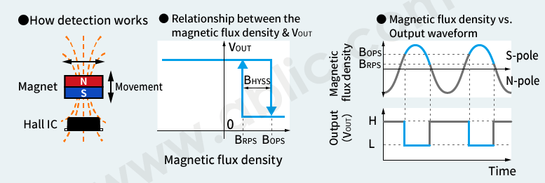
For this method, only one magnetic field pole (north or south) is detected, and on/off operation is performed according to the magnetic flux density to output a high or low level signal.
Omnipolar Detection
For this method, both magnetic field poles (north and south) are detected, and on/off operation is performed according to the magnetic flux density to output a high or low level signal.
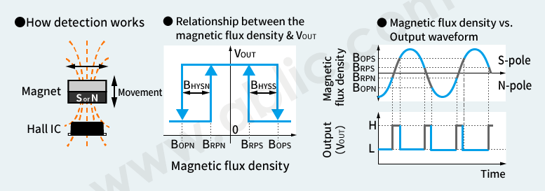
Bipolar Detection
For this method, both magnetic field poles (north and south) are detected in alternation, and on/off operation is performed according to the magnetic flux density and polarity to output a high or low level signal.
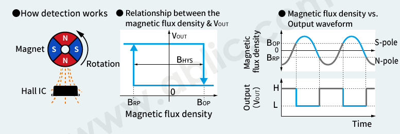
ZCLTM(Zero Crossing Latch) Detection
ZCL detects the point when the S-pole of the applied magnetic flux density changes to N-pole or vice versa, that is when there is a polarity change.
Optimized for brushless DC motor control, ZCL detection can easily prevent drops in motor efficiency resulting from temperature variations and manufacturing variations.
What is the ZCL Hall effect IC? | ZCL Hall Effect ICs Ideal for BLDC Motors
“ZCL” is a registered trademark of ABLIC Inc.
Let's reduce design man hours to create the ideal motor
with the World's first detection method
What ZCL Hall effect IC Can Do
How to select a suitable Hall effect IC
ABLIC offers a wide variety of Hall effect ICs on customers' demand. You can select a suitable Hall effect IC by considering order below.
| Applications | Automotive-use | General-use (Hi-Speed/Hi-Volt) | General-use (Small, Low IDD) |
|---|---|
| Detection method / Pole detection | Unipolar Detection (S-pole) | Unipolar Detection (N-pole) | Omnipolar Detection | Bipolar Detection | ZCL Detection |
| Operating environment | Operating temperature | Operating voltage |
| Package | SNT-4A | SOT-23-3 | SOT-23-3S |
| Output type | Output form | Output logic |
| Chopping frequency (current consumption) / Magnetic sensitivity | *Selectable on Selection Table |
ABLIC's Hall effect ICs
Latch Type
Latch Type
- Detection type
- VDD (V)
- Ta max. (°C)
- Package
- Datasheet
- ZCL
- 2.7 to 26
- 125
- TSOT-23-3S,
HSNT-6(2025)
- ZCL
- 2.7 to 26
- 150
- TSOT-23-3S
- Bipolar latch
- 3.5 to 26
- 125
- SOT-23-3S
- Bipolar latch
- 2.7 to 26
- 125
- SOT-23-3S
- Bipolar latch
- 2.7 to 26
- 125
- TSOT-23-3S,
HSNT-6(2025)
- Bipolar latch (2D)
- 3.8 to 26
- 125
- SOT-23-5,
HSNT-6(2025)
Switch Type
- Detection pole
- VDD (V)
- Ta max. (°C)
- Package
- Datasheet
- Omnipolar
- 2.7 to 26
- 125
- TSOT-23-3S,
HSNT-6(2025)
- S / N pole
- 3.5 to 26
- 85
- SOT-23-3
- S / N pole
- 2.7 to 26
- 125
- TSOT-23-3S,
HSNT-6(2025)