In the following, we describe how to select a reset IC (voltage detector or voltage monitoring IC).
A reset IC is an extremely simple IC, but if its features and additional functions are correctly used, it will enable highly accurate device monitoring and control.
Specifications to confirm
Confirm the voltage (= the voltage that should trigger a reset signal) you need to detect
Detection voltage
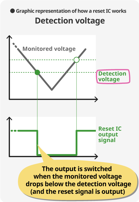
A reset IC generates a reset signal when the monitored voltage drops below the detection voltage.
The detection voltage of the reset IC can often be selected using a product option. For example S-809 Series the detection voltage can be selected in 0.1V steps between 1.3 - 6.0V.
Detection voltage accuracy
Detection voltage accuracy is an important specification in selecting a reset IC.
Since variations in temperature or manufacture cause errors that affect the detection voltage accuracy of the reset IC, detection voltage accuracy is indicated as ±xx%(mV). This makes it essential to take the amount of error into account when selecting a reset IC.
The graph below explains the impact caused by variations in detection voltage accuracy and hysteresis width.
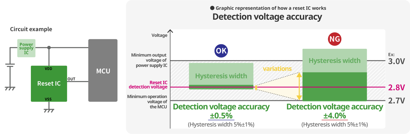
To use a reset IC in the circuit example pictured above, it is essential to select a reset IC whose detection voltage including any variations and hysteresis width is between the minimum output voltage of the power supply IC and the minimum operation voltage of the MCU.
For example, a reset IC with a detection voltage accuracy of ±0.5%, the detection voltage will be between the minimum output voltage of the power supply IC and the minimum operation voltage of the MCU even after taking account for variations and hysteresis width.
However, for a reset IC with a detection voltage accuracy of ±4.0%, it is reasonable to assume that when variations are at maximum, the detection voltage will not be between the minimum output voltage of the power supply IC and the minimum operation voltage of the MCU. If the release voltage is higher than the minimum operation voltage of the power supply IC, it will not be possible to disable MCU reset status.
Thus it is easy to understand that you need to select a reset IC with a detection accuracy better than ±4.0% for voltage detecting of this MCU.
Confirm the voltage that should clear the reset signal
Release voltage
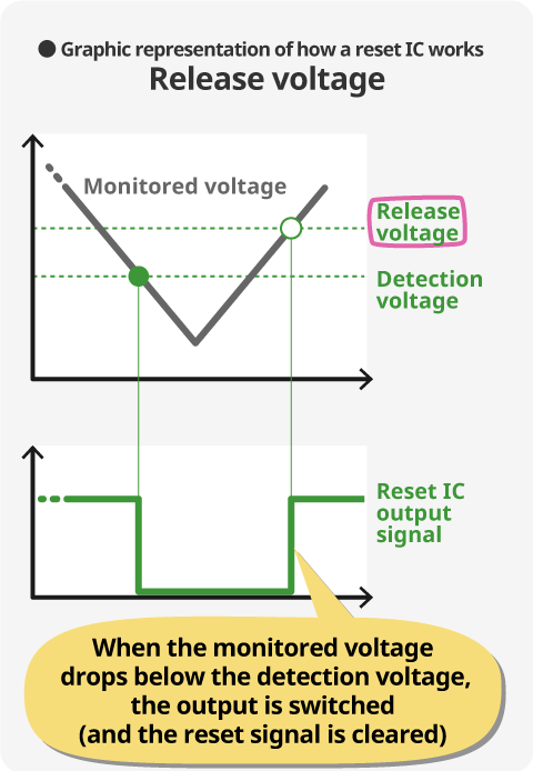
The reset IC clears the reset signal when the monitored voltage rises above the release voltage. Most reset ICs provide a hysteresis width for the detection voltage and this determines the release voltage.
Hysteresis width
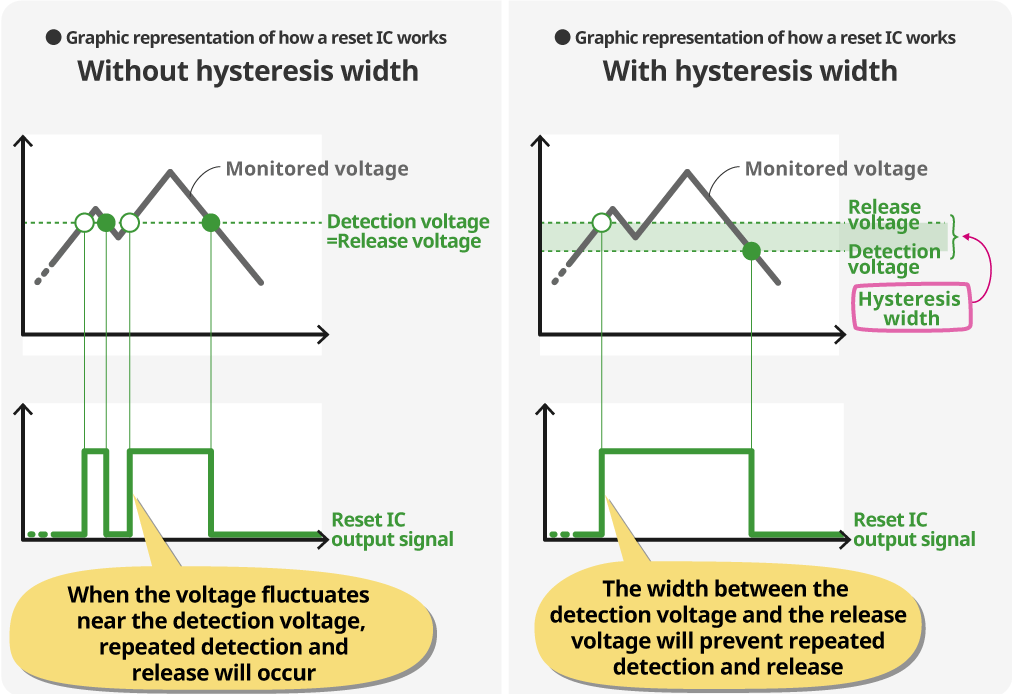
Hysteresis width indicates the difference between the release voltage and the detection voltage.
If no hysteresis width has been provided, the output of the reset IC will repeatedly and rapidly switch between H and L when the monitored voltage fluctuates near the detection voltage, which may cause subsequent systems to operate unstably.
Hysteresis width prevents unnecessary detection and release of the reset IC.
However, in automotive applications reset ICs without hysteresis width is sometimes required.
This has something to do with “detection voltage accuracy” above, when MCU requirements are tough, or when the width between the minimum operation voltage of the MCU and that of the supply IC is extremely small, use of a reset IC without hysteresis width is effective.
Selecting a reset IC based on hysteresis width
With hysteresis
Without hysteresis
Confirm the delay time
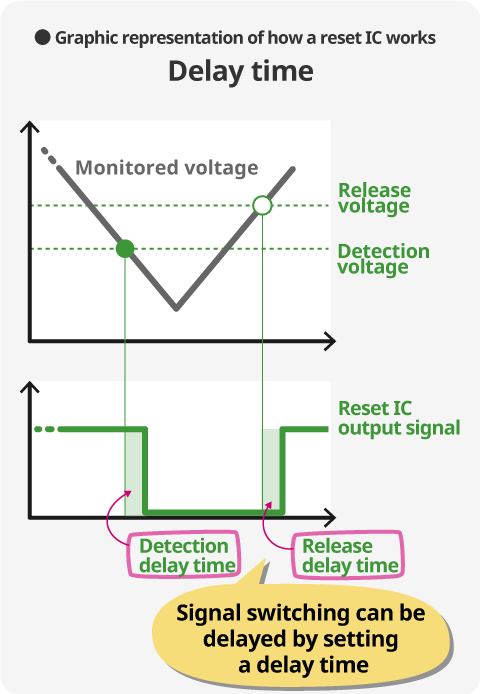
The delay time of the reset IC includes the “detection delay time” and the “release delay time.” The “detection delay time” indicates the time from when the monitored voltage drops below the detection voltage and until the reset signal is output, while the “release delay time” indicates the time from when the voltage reaches the detection voltage and until the reset signal is cleared. (The term delay time, when used alone normally indicates the latter, that is, “release delay time.”)
The user can select from a product series of reset ICs without delay time, with a built-in delay circuit where the delay time is set with an external capacitor, with a built-in delay circuit where the delay time is set internally.
When is a release delay time necessary?
The main reason for setting a release delay time is to ensure that MCUs and other systems start up when power has stabilized. Some MCUs determine the time it takes power to reach operating voltage range and require that reset status be maintained until the MCU can be normally initialized.
When is a detection delay time necessary?
When monitoring voltage in a very noisy environment, the noise may cause the power supply voltage to drop below the detection voltage for very short time periods. If such voltage drops are detected as voltage errors, an error reset state that may prevent the system from operating will occur.
A reset IC with a detection delay time is able to ignore such momentary voltage drops.
Reset ICs that can set a release delay time: 3 series
Low current consumption 270nA typ.
Detection voltage 1.3~6.0V
Detection delay time can also be set
No release delay Reset IC
Ultra low current consumption of 350nA typ.
Detection voltage 0.8~6.0V
SENSE detection type
Selecting a detection type
There are a number of reset IC detection types, which differ depending on which pin of the reset IC the input voltage is monitored.
A criterion used in selecting ICs is determining whether it is necessary to output a reset signal also when the monitored voltage drops below the minimum operation voltage of the reset IC. If this is a requirement, a SENSE detection type is a good choice.
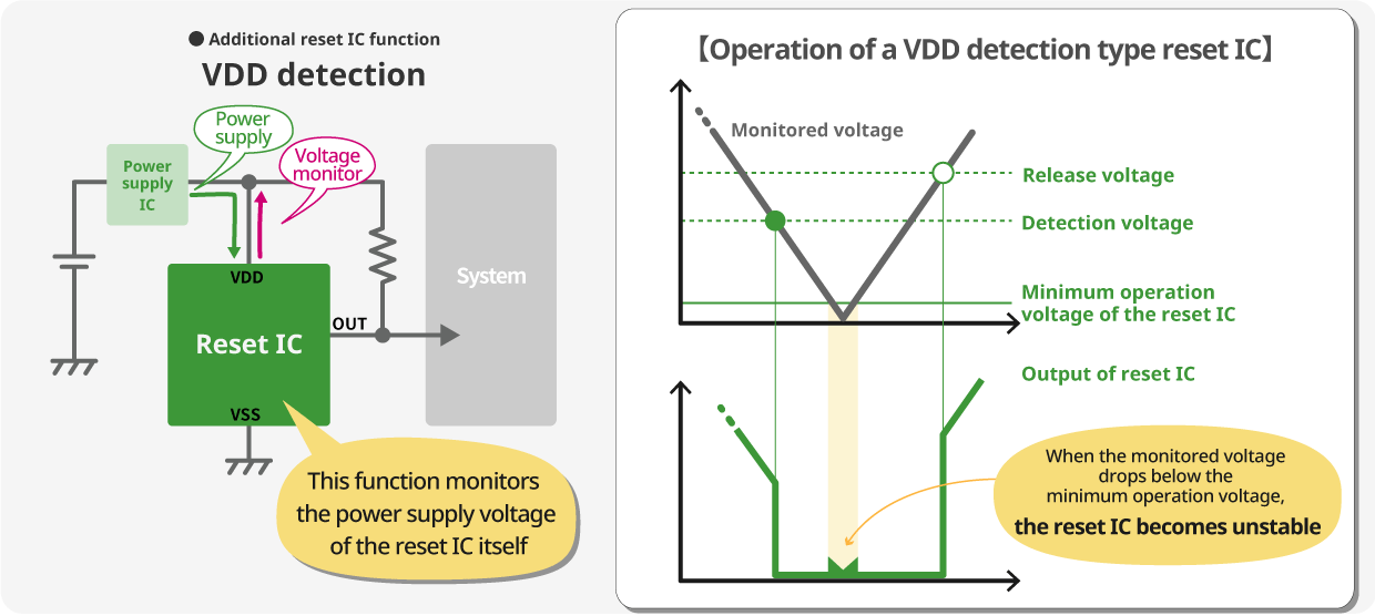
VDD detection
A VDD detection type monitors the power supply voltage input to the VDD pin of the reset IC. Its circuit configuration is simple and if the monitored voltage, that is the power supply voltage, drops below the minimum operation voltage of the reset IC, reset IC will not operate stably and the output signal also becomes unstable.
SENSE detection
A SENSE detection type monitors and detects the voltage input to the SENSE pin not the power supply voltage of the reset IC. By providing an input pin for the monitored voltage other than the VDD pin (= power supply pin), the reset IC is shielded from the monitored voltage and even if the monitored voltage drops to 0V, the IC can still be depended on to output a reset (signal).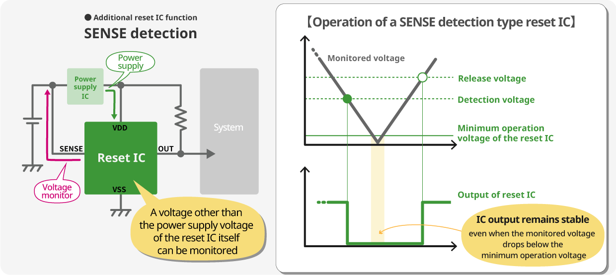
VDD detection type reset IC: 3 series
Detection voltage 1.3~6.0V
Detection voltage 0.8~4.6V
Detection voltage 2.2~6.0V
SENSE detection type
Detection voltage 1.0~5.0V, No delay
Detection voltage 1.0~5.0V, with delay
Detection voltage 3.0~10V
Confirm and output logic
Output form:Nch open-drain output, CMOS output
There are two reset IC output types: Nch open drain output products and CMOS output products.
If the reset IC and the MCU that receives the reset signal share the same type of power system, a CMOS output product can be used, otherwise an Nch open drain output product should be used.
Selecting an ideal reset IC based on additional functions
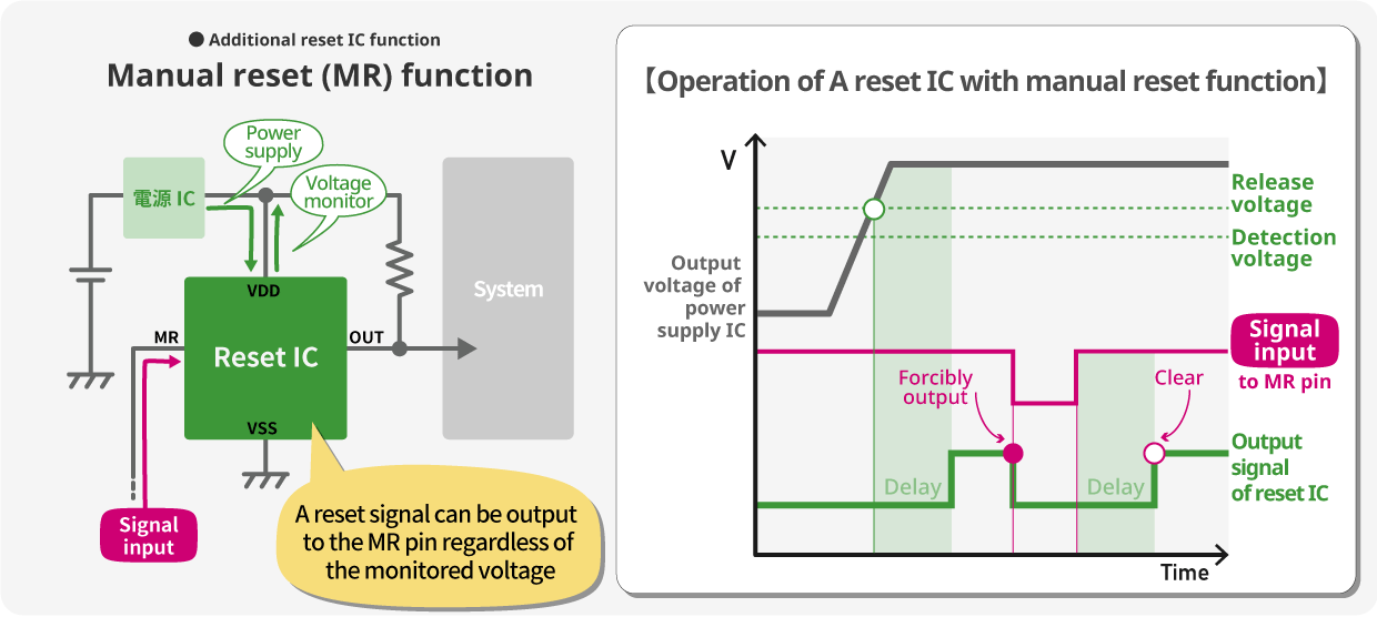
Manual reset function
The manual reset function can forcibly output a reset signal by inputting a signal to the MR (manual) pin on the reset IC.
This function makes it possible to switch the reset signal regardless of voltage. For example, by connecting an MR pin to an external switch of an electronic device, the user can freely control the output of the reset IC.
Reset IC with manual reset function
ABLIC's Reset ICs

As the leading reset IC company, ABLIC has a 35-year manufacture and development track record with a share of the market that is second to none in the industry.
(*According to ABLIC market data)
If you are looking for a reset IC, ABLIC's ICs come highly recommended.
View all products
If you're interested in selecting products based on specifications, exploring detailed datasheets, or making purchases online, please visit here.
Voltage Detectors (Reset ICs) for General Use
Automotive Voltage Detectors (Battery Monitoring & Reset ICs)
High accuracy ±0.5%