What is a switching regulator?
1. Basic role
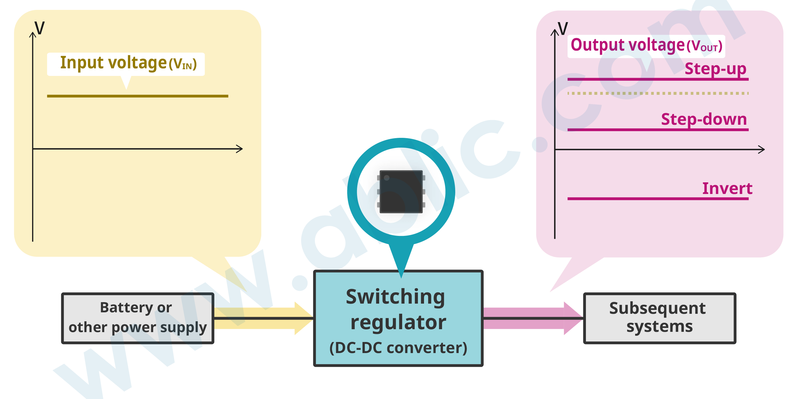
A switching regulator (DC-DC converter) is a regulator (stabilized power supply). A switching regulator can convert input direct current (DC) voltage to the desired direct current (DC) voltage.
In an electronic or other device, a switching regulator takes the role of converting the voltage from a battery or other power source to the voltages required by subsequent systems.
As the illustration below shows, a switching regulator can create an output voltage (VOUT) that is higher (step-up, boost), lower (step-down, buck) or has a polarity different than that of the input voltage (VIN).
2. Switching regulator types
A switching regulator is a regulator (stabilized power supply) and there are the following switching regulator types.
| Regulator (stabilized power supply) |
Switching regulator (DC-DC converter) |
Isolated switching regulator | ||
| Non-isolated switching regulator | ||||
| Linear regulator |
Shunt regulator | |||
| LDO regulator | ||||
This article provides a detailed explanation of the features and operation of “non-isolated switching regulators.”
Non-isolated switching regulators also use the following systems and operating modes.
| Voltage conversion system | Step-down, step-up, step-up/down, invert |
|---|---|
| Rectification system | Asynchronous, synchronous |
| Operating mode | PFM, PWM, PFM/PWM switching |
Click the term to find out more.
3. Switching regulator characteristics
The following provides a description of non-isolated switching regulator characteristics.
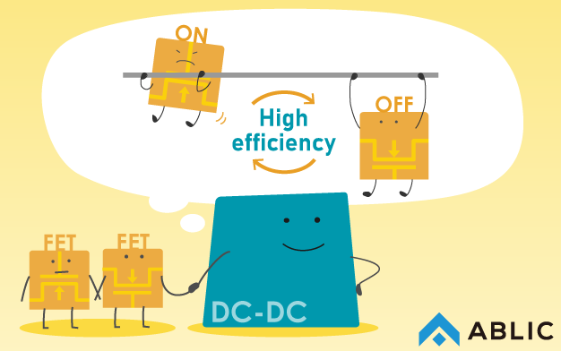
High efficiency
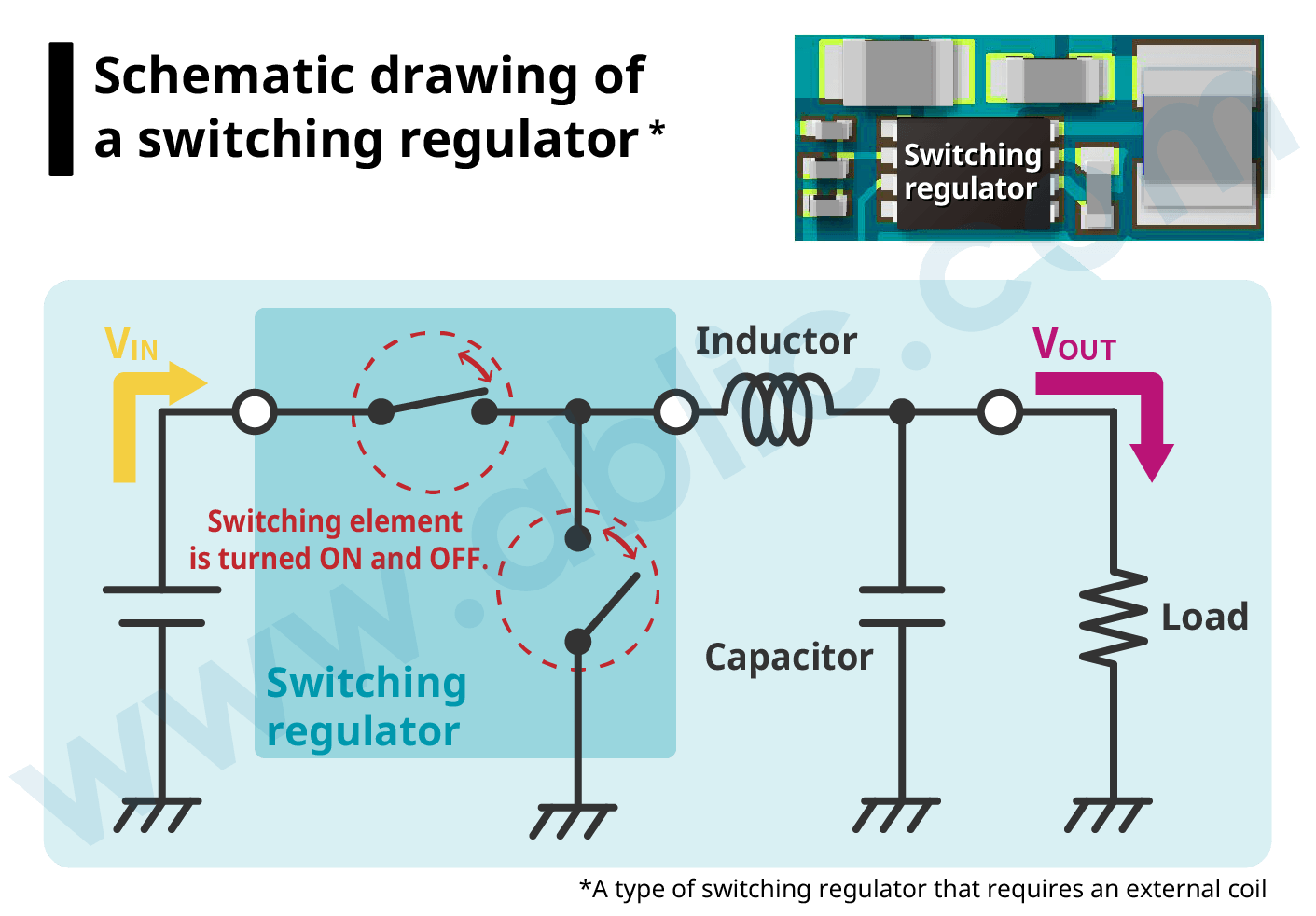 By turning a switching element ON and OFF, a switching regulator enables high-efficiency electricity conversion as it supplies the required amount of electricity only when needed.
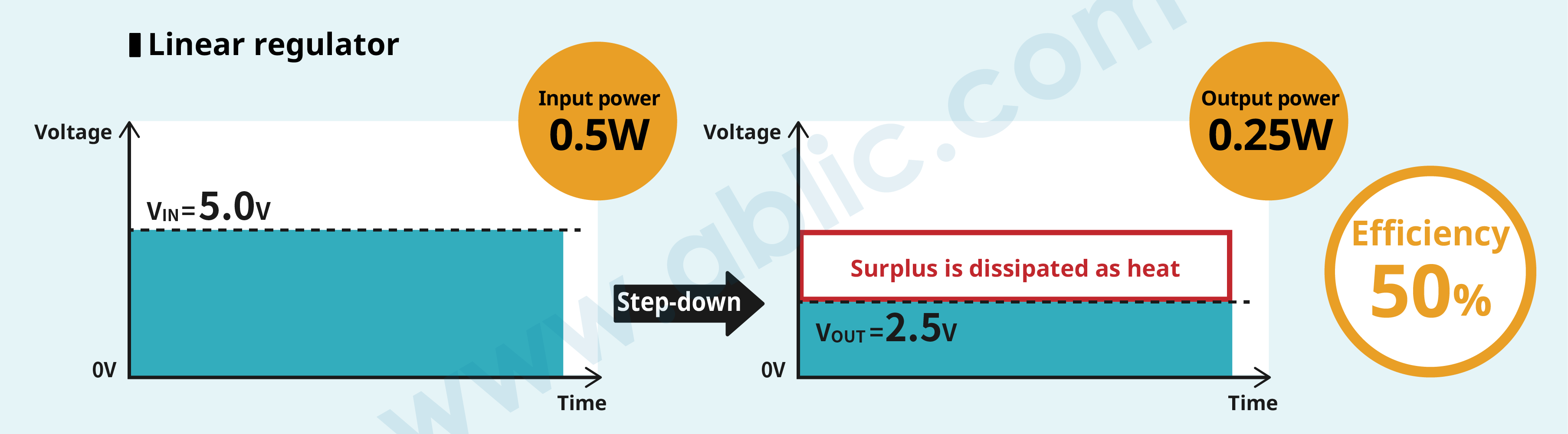
A linear regulator is another type of regulator (stabilized power supply), but because it dissipates any surplus as heat in the voltage conversion process between VIN and VOUT, it is not nearly as efficient as a switching regulator.
The easiest way of explaining how a switching regulator can efficiently convert voltage is comparing it to a linear regulator.
For example, if the input voltage (VIN) is 5.0V, output voltage (VOUT) is 2.5V and load current (IOUT) is 0.1A,
In a linear regulator
Input power = Input voltage × Load current
= 5.0V × 0.1A
= 0.5W
Output power = Output voltage × Load current
= 2.5V × 0.1A
= 0.25W
Since efficiency = Output power ÷ Input power, the efficiency of a linear regulator is 50%.
A switching regulator, however, controls the period when the input voltage is supplied by turning the switching element ON and OFF so that VOUT becomes 2.5V. This time period when input voltage is supplied is
VOUT VIN = 2.5V 5.0V = 1 2
From this we can see that voltage is supplied for half a period. Similarly, if you try to obtain efficiency from the input and output power, we get the following:
Input power = Input voltage × Load current × 1 2
= 5.0V × 0.1A × 1 2
= 0.25W
Output power = Output voltage × Load current
= 2.5V × 0.1A
= 0.25W
Calculating efficiency from the above equation: Efficiency = Output power ÷ Input power, we obtain a value of 100%. This is why a switching regulator provides high efficiency.
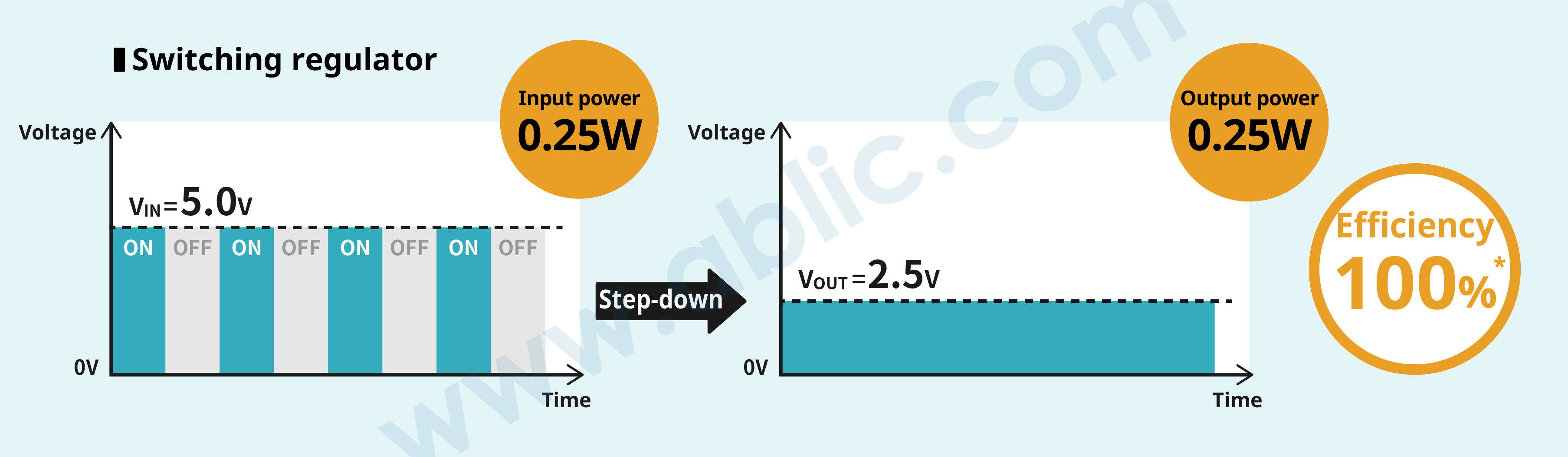 *Since there are actual losses, the true figure is around 90%.
Noise
The switching element ON/OFF operations in a switching regulator cause sudden changes in voltage and current, and parasitic components that generate ringing, all of which introduce noise in the output voltage.
Using an appropriate board layout is effective in mitigating noise. For instance, optimizing the placement of capacitor and inductor and/or wiring. For more information on the mechanism of how noise (ringing) is generated and how it is controlled, refer to the Application Note “Step-Down Switching Regulator Noise Countermeasures.”
Comparing switching regulator and linear regulator characteristics
| Switching regulator | Linear regulator | |
| Output voltage conversion system | Step-down, step-up, step-up/down, invert | Step-down only; VOUT must be less than VIN |
| Efficiency | High (negligible heat generation) | Comparatively low (high heat generation) Low when the difference between input and output voltage is large |
| Output current | Large (high efficiency means high current) | Small |
| Noise | Large | Small |
| Output ripple | Present | None |
| Required external components | Many CIN, COUT, L, (SBD) |
Few CIN, COUT |
The ideal switching regulator for any application
Ultra-compact DC-DC converter ideal for automotive cameras
| Rating 45V, low ripple | Webshop (Sample purchase) |
|---|---|
For industrial equipment and housing appliances
| 12V / 24V input, ultra-compact | Webshop (Sample purchase) |
|---|---|
For IoT / wearable devices
| Ultra-high efficiency at light load, compact | Webshop (Sample purchase) |
|---|---|
> Operating principles and modes of a switching regulator
> Introduction – Switching Regulator ICs (DC-DC Converter ICs)