
Operating principles and modes of a switching regulator
1. Principle of output voltage conversion of a switching regulator
This section explains the principle of voltage conversion of a step-down switching regulator.
Below are a schematic drawing of a switching regulator and an overview of switching regulator operation. As shown in the drawing below, a switching regulator outputs the desired DC voltage by converting an input voltage (VIN) to a pulse by alternately switching SW1 on input voltage side (VIN) and SW2 on GND side ON / OFF and removing the AC components using an LC filter.
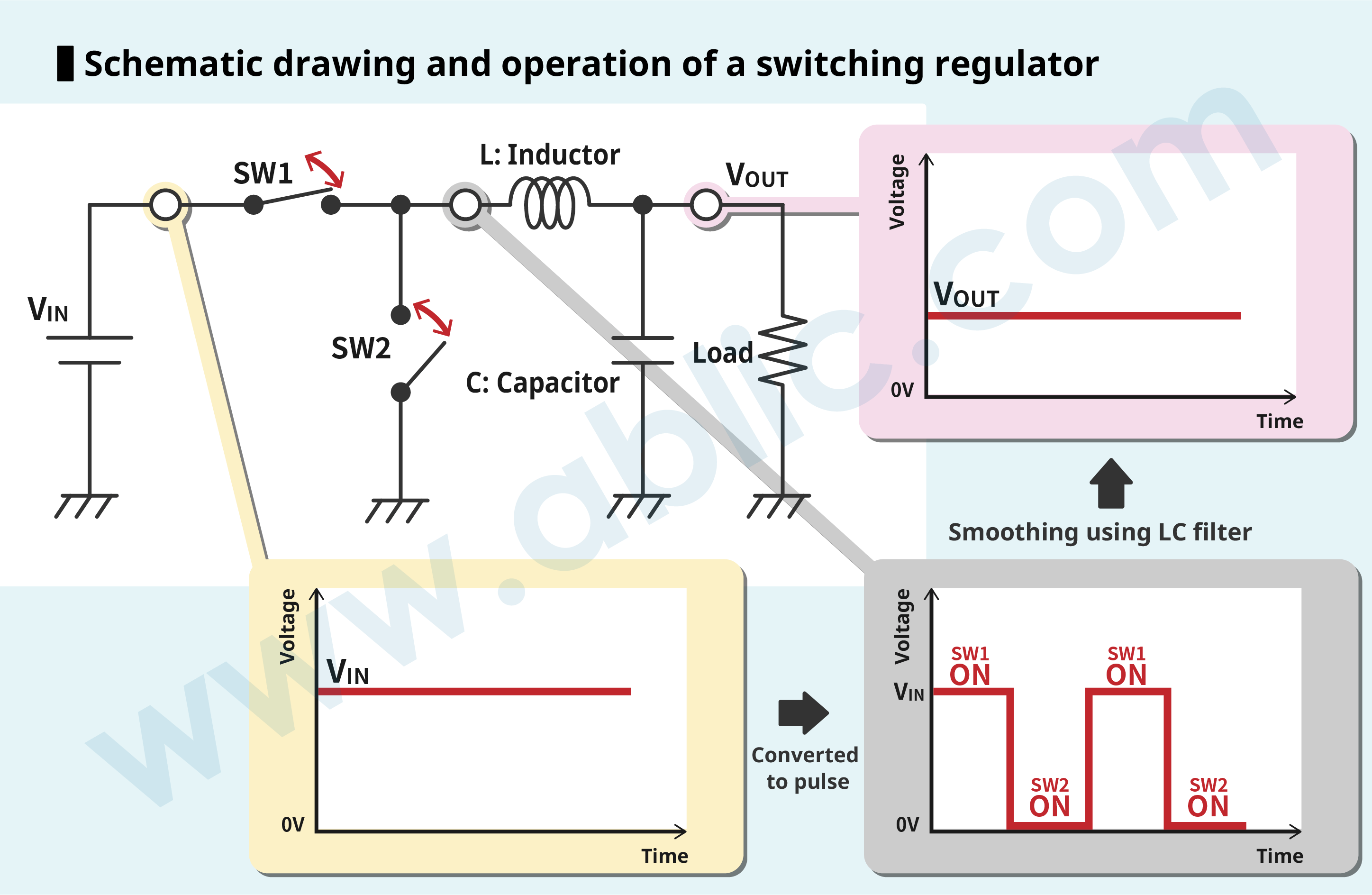
1. VIN is input to the inductor when SW1 goes ON and SW2 goes OFF.
2. The inductor is connected to GND when SW1 goes OFF and SW2 goes ON.
3. The LC filter smooths the pulse and outputs a DC voltage.
Normally, SW1 is a MOS FET, while SW2 is a diode or MOS FET.
Asynchronous rectification uses a MOS FET in SW1 and a diode in SW2, while synchronous rectification uses a MOS FET in both SW1 and SW2.
The low loss in SW2 in synchronous rectification ensures greater efficiency than that of asynchronous rectification.
2. Switching regulator operating modes
There are two types of output voltage control methods for switching regulators: PWM control and PFM control.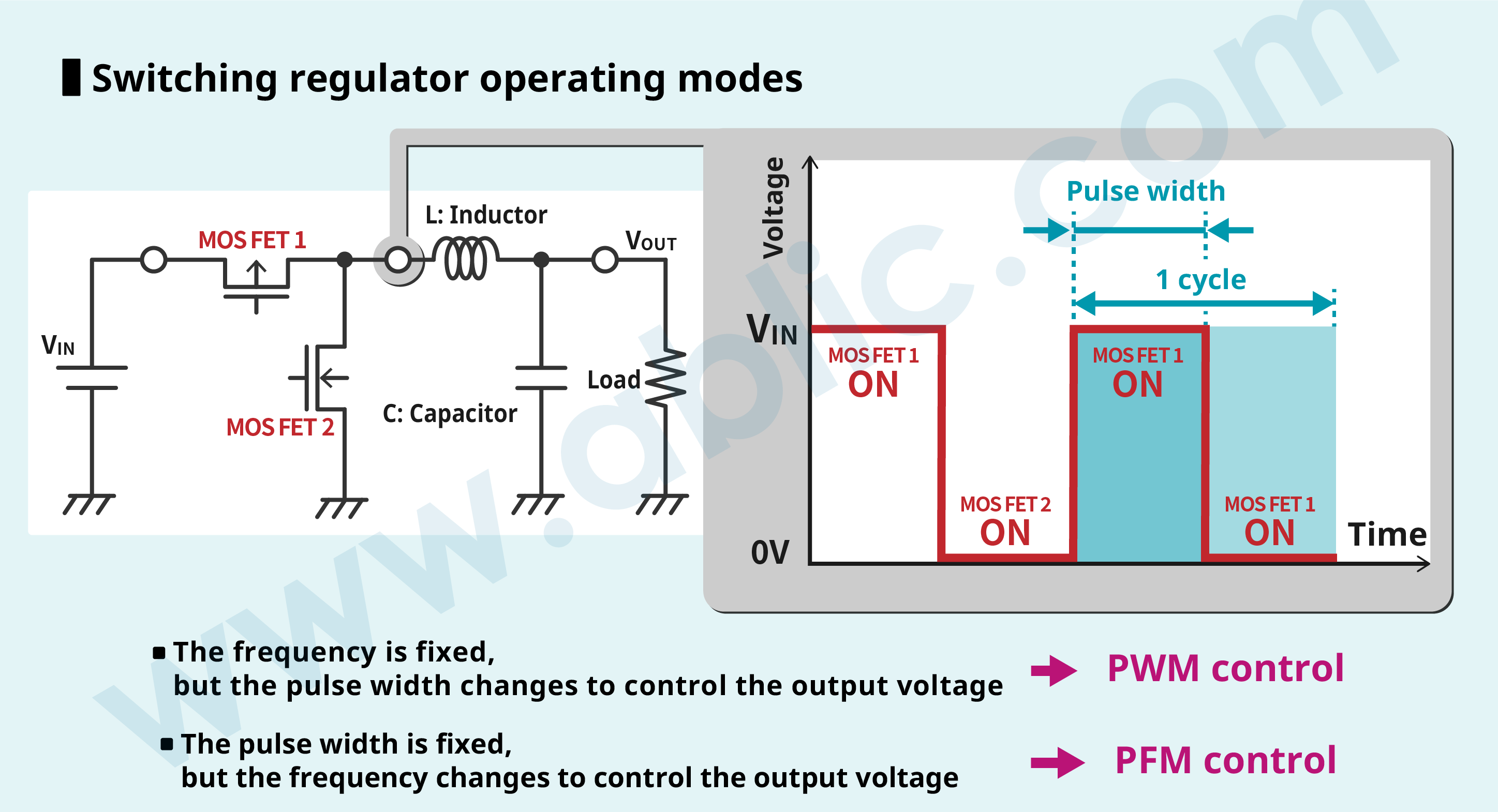
PWM control
The PWM control is the most common output voltage control method used by switching regulators.
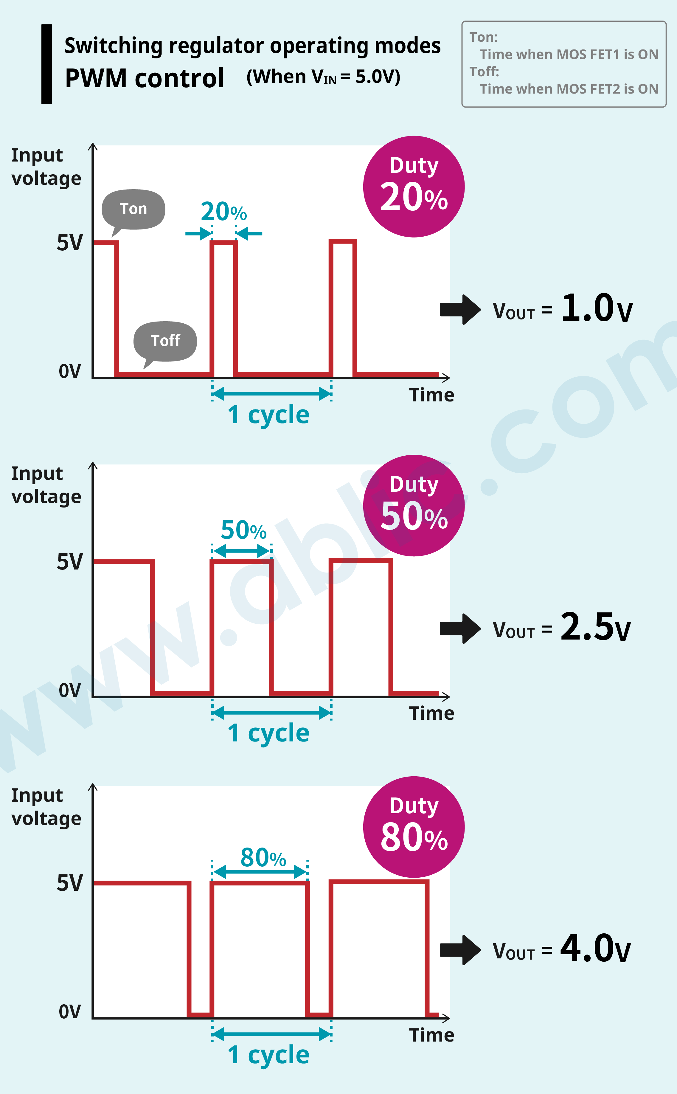
In Pulse Width Modulation (PWM), the frequency is fixed while pulse width changes to control the output voltage.
The time when MOS FET1 is ON is Ton, the time when MOS FET2 is ON is Toff, the time ratio when MOS FET1 is ON during 1 cycle (Ton + Toff) is called Duty. This relationship can be expressed by the following equation.
Duty = Ton (Ton + Toff)
In PWM control, the output voltage (VOUT) is determined by the input voltage (VIN) and the ratio of the time (Duty) when MOS FET1 is ON (Ton), which is expressed by the equation below.
Output voltage = Input voltage × Duty
In PWM control, operation is performed according to a constant frequency regardless of the extent of load current so the switching count per time unit (ON/OFF count of MOS FET1 and 2) is constant.
The advantage of this control method is that countermeasures against switching noise are comparatively simple. A drawback is that the efficiency drops significantly since switching loss becomes dominant at light load current.
PFM control
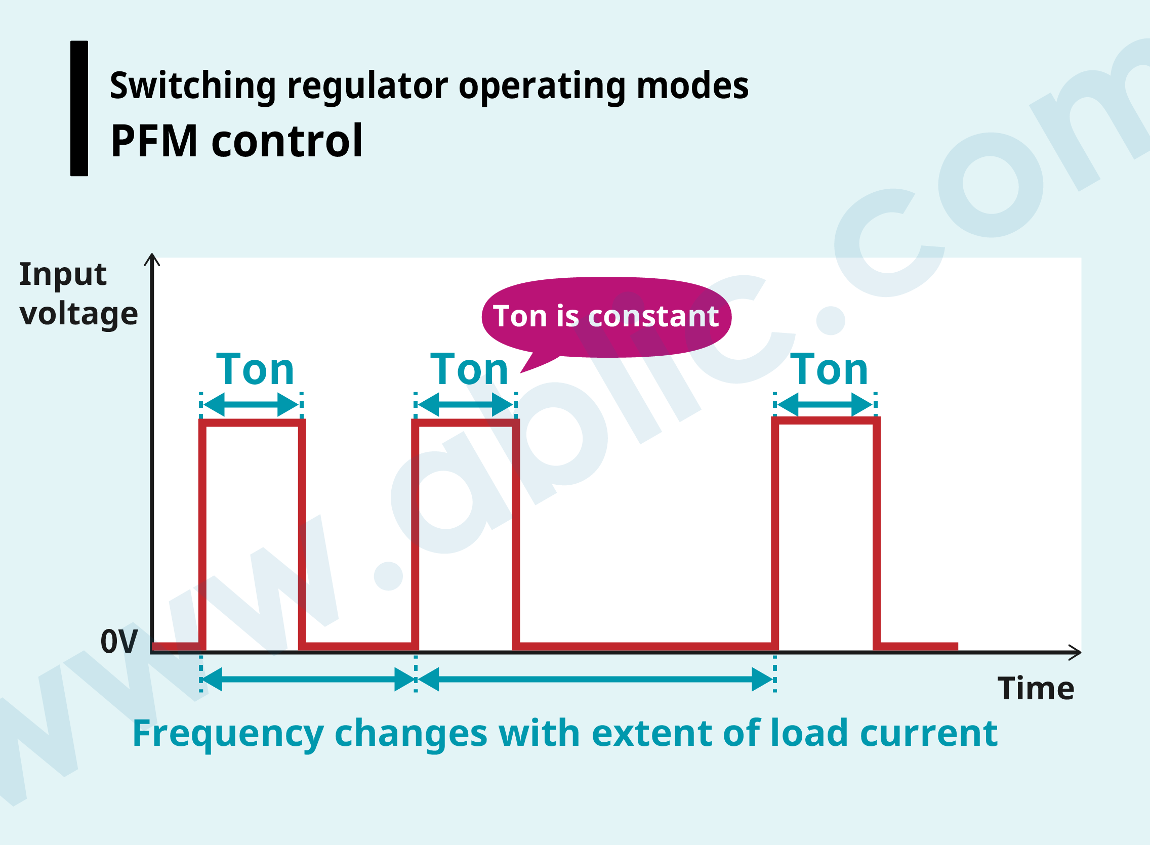
In Pulse Frequency Modulation (PFM), pulse width is fixed while the frequency changes to control the output voltage.
The frequency drops at light load current and rises at heavy load current to minimize switching loss and maintain high efficiency regardless of load current.
However, since the switching frequency changes with the extent of load current, the generated switching noise waveform is not constant making noise filtering difficult.
PFM/PWM switching control
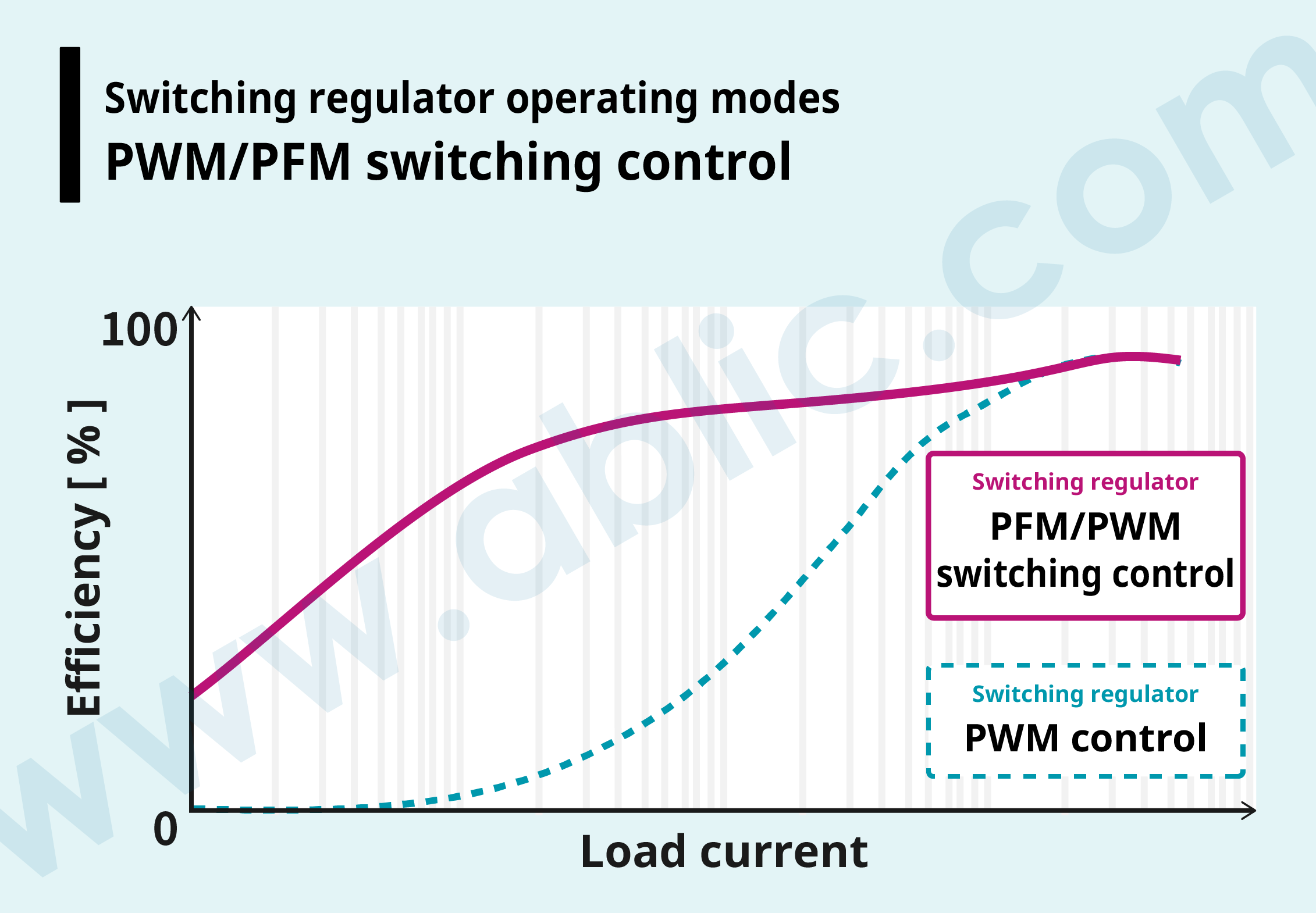 As explained earlier, the efficiency of a switching regulator with PWM control drops significantly since switching loss becomes dominant at light load current.
A switching regulator operating with “PFM/PWM switching control” where PWM control is selected at heavy load current and PFM control at light load current enables high efficiency across a wide load current range.
The ideal switching regulator for any application
Ultra-compact DC-DC converter ideal for automotive cameras
| Rating 45V, low ripple | Webshop (Sample purchase) |
|---|---|
For industrial equipment and housing appliances
| 12V / 24V input, ultra-compact | Webshop (Sample purchase) |
|---|---|
For IoT / wearable devices
| Ultra-high efficiency at light load, compact | Webshop (Sample purchase) |
|---|---|
> What is a Switching Regulator?
> Introduction – Switching Regulator ICs (DC-DC Converter ICs)