Table of Contents
1. ZCLTM Hall Effect ICs Ideal for Building High-speed BLDC Motors!
Low delay allows elimination of synchronization error and detection delay!
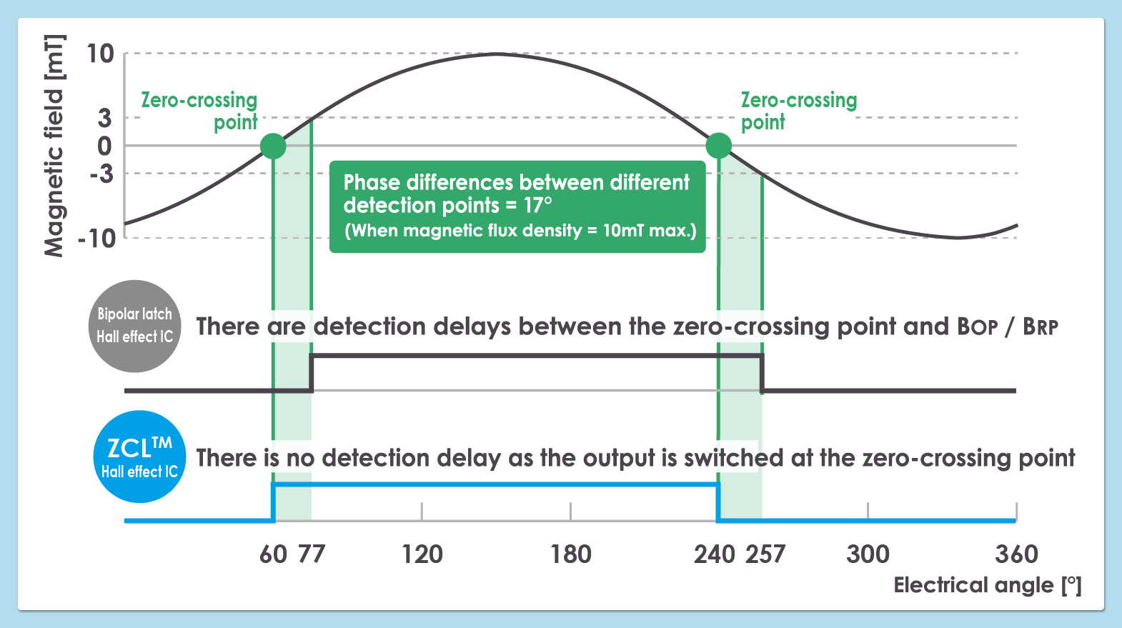
An increase in detection delay time in a BLDC motor (brushless DC motor) increases the deviation angle.
An increase in speed per revolution makes delay time the greater part of detection time. This is more noticeable at higher speeds as the detection limit of the rotor magnetic field is approached.
A bipolar Hall effect latch IC has theoretically a delay from the rotor zero-crossing point (where flux density is zero) to the operating point (BOP) / release point (BRP). This is the detection delay.
The ZCLTM Hall effect IC detects the direction of the magnetic flux (toward the S-pole or the N-pole) at the rotor zero-crossing point to determine the output. This eliminates the aforementioned delay and enables faster rotation.
However, there is a delay between the detection of a polarity change in the IC and until the IC output changes. The output delay time of ABLIC's bipolar Hall effect latch ICs and ZCLTM Hall effect ICs is currently 8μs.
Detection and delay differences between bipolar Hall effect latch ICs and ZCLTM Hall effect ICs
The following table shows the impact of IC delay on phase.
| IC type | Detection delay from zero-crossing point to BOP |
Detection delay from BRP to zero-crossing point |
Conditions (Maximum magnetic flux density is 10mT) |
|---|---|---|---|
| Bipolar Hall effect latch IC |
Equivalent to 17° | Equivalent to 17° | BOP=3.0mT |
| ZCLTM Hall effect IC | 0° (No delay) | 0° (No delay) | BZ=0mT* |
BZ: Zero-crossing latch point (the value of magnetic flux density value at which polarity changes are detected according to the magnetic flux density applied to the IC)
Difference in range of variation between bipolar Hall effect latch ICs and ZCLTM Hall effect ICs
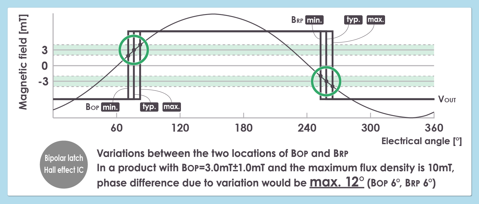
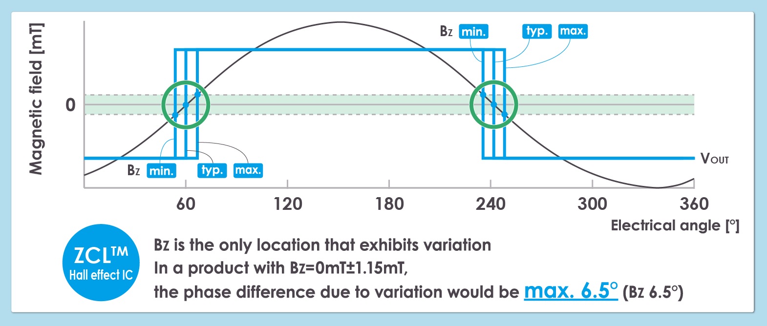
The following table shows the impact of variation in the sensitivity of each IC on phase (at a maximum flux density of 10mT).
| IC type | Variation in BOP (3.0mT±1.0mT) |
Variation in BRP (-3.0mT±1.0mT) |
Variation in BZ (0mT±1.15mT) |
|---|---|---|---|
| Bipolar Hall effect latch IC | Equivalent to 6° | Equivalent to 6° | ― |
| ZCLTM Hall effect IC | ― | ― | Equivalent to 6.5° |
2. ZCLTM Hall effect ICs Need No Calibration After Assembly!
Greater flexibility since there is no need to worry about UVW phase difference!
Many customers make advance angle adjustments to achieve maximum motor torque. Maximum torque is achieved when the phase of the magnetic field is delayed by 90 degrees relative to the phase of the coil magnetic field.
Adjustments such as measuring maximum torque positions and recording delay times in MCU memory are probably performed on many production lines.
As the ZCLTM Hall effect IC operates based on the zero-crossing point, there is no need to adjust the UVW phase difference compensation due to the delays or variations in sensitivity from the zero-crossing point to the BOP / BRP.
Specifically, the output delay time specific to the IC is simply preset on the MCU side. We believe this will contribute to increase productivity and reduce costs.