Table of Contents
- Advantages of Position Sensing Using Linear Hall Effect Sensor ICs
- Magnets Suitable for Position Sensing (Rotation/Sliding Detection)
- Advantages of Non-Contact Position Sensing
- Alternative Uses - Application Examples for Rotational/Sliding Amount Detection
- Need Help with Magnetic Design?
- Try Out ABLIC's Linear Hall Effect Sensor ICs
1. Advantages of Position Sensing Using Linear Hall Effect Sensor ICs
Converting Magnetic Flux Density to Analog Voltage
A linear Hall effect sensor IC detects the magnetic flux density of a magnet and outputs an analog voltage proportional to that level. By monitoring the magnetic flux density of a magnet placed on a moving part, it can detect even very small movements.
Depending on the magnet type (shape and magnetization pattern, such as horizontal or vertical orientation), it can be used in a wide range of applications, including linear and rotational position sensing.
This page introduces position sensing using ABLIC's single-axis linear Hall effect sensor IC S-5611A Series.
The S-5611A Series features a fast response, low noise, and a programmable output voltage gain, enabling highly accurate sensing.
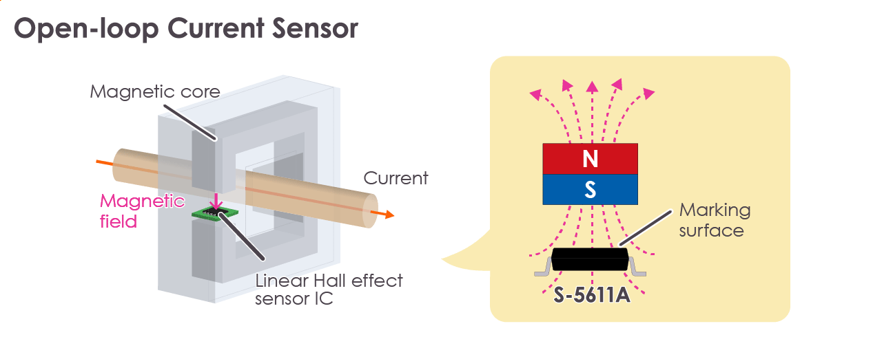
Usability as Both a Current Sensor and a Position Sensor
A linear Hall effect sensor IC can function as both a current sensor and a position sensor.
When Used as a Current Sensor
The IC detects the magnetic flux density generated in a wire via a soft ferrite core and outputs a corresponding analog voltage, which is then used to determine the current level.
When Used as a Position Sensor
A magnet is attached to a moving part, and the IC detects changes in magnetic flux density. As with current sensing, the IC outputs an analog voltage proportional to the magnetic flux density level.
In position sensing, selecting the appropriate magnet type enables control that responds to subtle changes in magnetic flux density. The direction of the magnet's magnetic force is called the magnetization direction, and it comes in two types: horizontal and vertical. By optimizing this magnetization direction together with the mechanical structure, various applications become possible, such as linear and rotational position sensing.
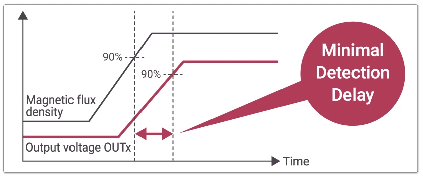
Compared to ICs that use DSP (Digital Signal Processor) processing, such as those used for absolute angle sensors, a major advantage of the S-5611A is its much faster detection speed because it processes signals in the analog domain. This industry's top-class*1 fast response (1.25μs*2) significantly contributes to reducing detection delay time.
Furthermore, because sensors requiring DSP processing involve higher costs, using the S-5611A also helps optimize overall system cost.
*1 Based on our research *2 Value in the 400kHz frequency bandwidth
Response Time Comparison with Absolute Angle Sensors Featuring DSP and Other Digital Computation Functions
| IC Category | Linear Hall Effect Sensor IC (S-5611A, ABLIC) | Absolute Angle Sensor (Company A) | Absolute Angle Sensor (Company B) |
|---|---|---|---|
| Equivalent to Detection Delay Time (typ.) | 1.25μs | 100μs (Propagation delay) | 290μs (Refresh rate) |
2. Magnets Suitable for Position Sensing (Rotation/Sliding Detection)
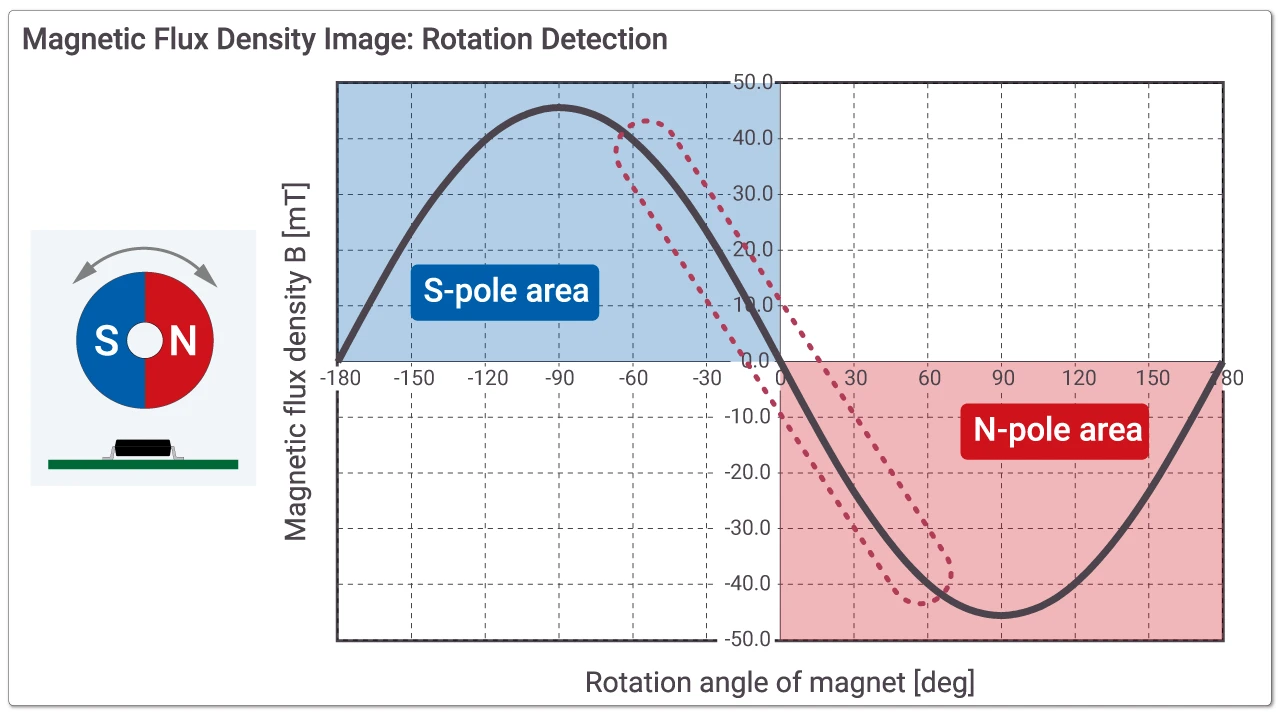
Magnets Suitable for Rotation Detection
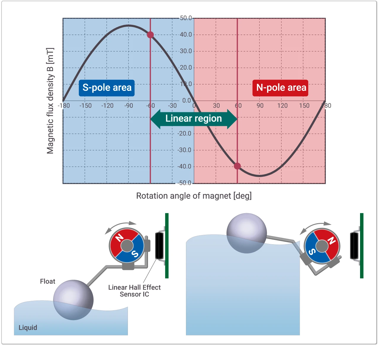
Magnets for rotation detection are circular magnets magnetized so that the S and N poles are distributed from the center.
When the magnet rotates one full turn, the magnetic flux density detected by the linear Hall effect sensor IC follows a sine curve. For position detection, the highly linear portion around the center voltage of the output waveform is used. The linear voltage (analog voltage) output is centered at the center voltage (default 2.5V), where the S pole produces a positive deviation, and the N pole produces a negative deviation.
Within a rotation angle of approximately 120° or less, the IC can serve as a lower-cost alternative to absolute angle sensors or rotary encoders, helping reduce overall system cost.
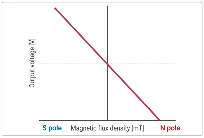
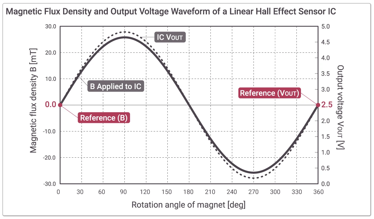
Magnetic Flux Density Received from Magnet vs. Output Voltage
The figure below illustrates the relationship between the magnetic flux density applied to the linear Hall effect sensor IC (S-5611A) and its corresponding output voltage. The solid line represents the magnetic flux density applied to the IC, and the dashed line represents the IC's output voltage.
The output voltage is centered around a reference voltage of 2.5V (2.5V ± 2.5V).
In this example, when the IC receives a maximum magnetic flux density of approximately 26mT, it outputs about 4.8V with a gain setting of 90mV/mT. This means that the output voltage changes by 90mV for every 1mT change (increase or decrease) in the magnetic flux density applied to the IC.
*The reference voltage is programmable.
Magnets Suitable for Sliding Detection
For sliding detection, magnets with either a horizontal or vertical magnetization can be used.
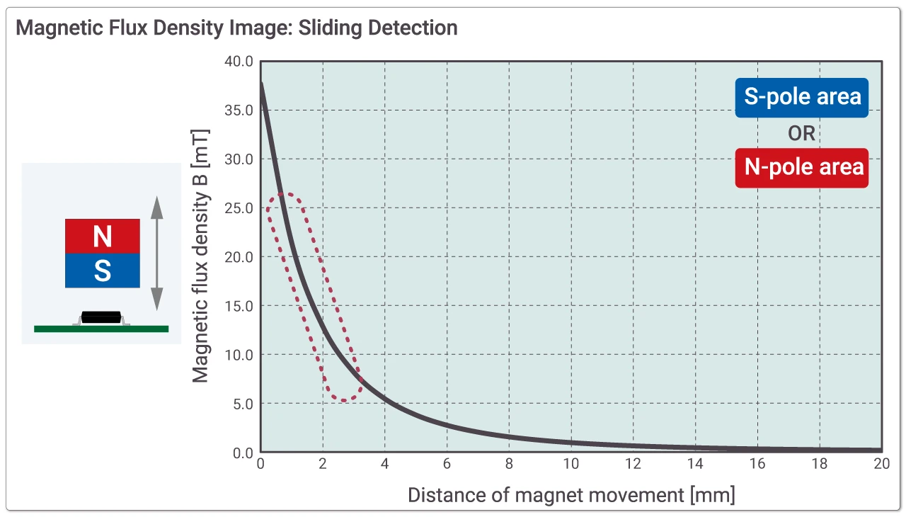
When the magnet moves closer to the IC, the output voltage increases (due to higher magnetic flux density), and when it moves away, the voltage decreases (lower flux density). Changing the magnetization direction or the size of the magnet allows the system to support a variety of movement patterns.
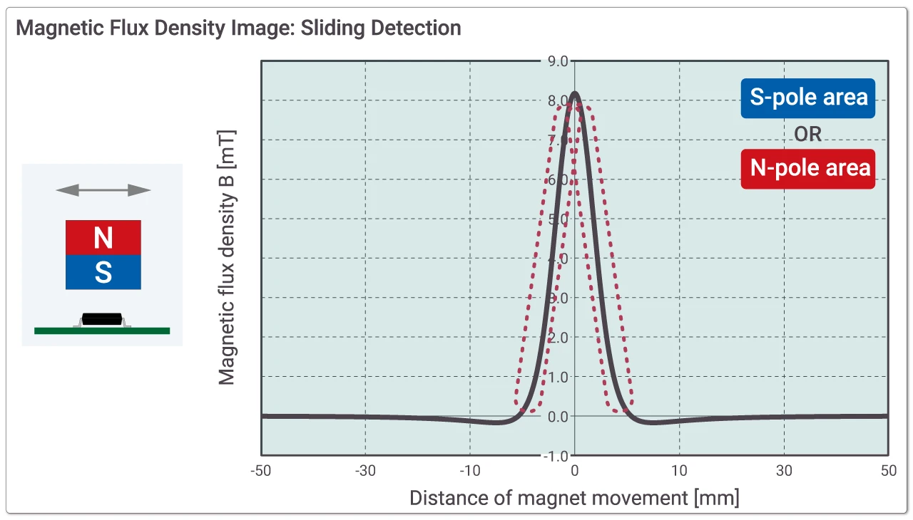
The figure below shows the output waveform for sliding detection. By using the dashed area of the output waveform, which is centered around the midpoint of the output voltage, linear sensing becomes possible. In addition, adjusting the magnet width allows the magnetic flux density characteristics to become either steeper or more gradual.
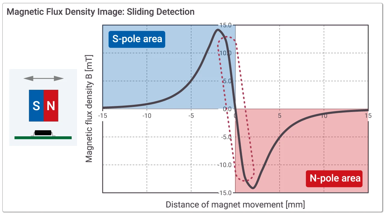
Magnetic Flux Density Illustration for Parallel and Vertical Movement Detection
3. Advantages of Non-Contact Position Sensing
Eliminating Design Concerns for Mechanical Volume Controls, Pedals, and Similar Components
No Risk of Contact Failure
The resistor elements in mechanical volume controls (contact-type volume adjustment components) can become unstable over time due to degradation. In contrast, a linear Hall effect sensor IC detects position without physical contact, making it immune to contact failure.
Stable Operation Even in Harsh Environments
Stable detection is possible even in harsh environments exposed to dust, sand, or water when the magnet and the IC are sealed with molding or coating. This eliminates concerns that the degree of rotation or sliding may not be detected properly. Furthermore, applications that allow the replacement of multiple Hall switches with a single linear Hall effect sensor IC are also possible.
4. Alternative Uses - Application Examples for Rotational/Sliding Amount Detection
Multi-Contact Switches (Shift Lever/DMM (Digital Multimeter))
When Used as a Selector
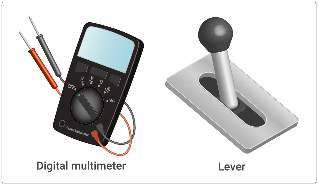
Position detection is possible by dividing the linear detection range of the linear Hall effect sensor IC so that multiple positions can be distinguished. A voltage range is preset for each switching position, and the IC outputs a voltage within that range. By having the MCU monitor this voltage, non-contact position determination becomes possible.
Because there is no concern about contact failure, this method offers extremely high durability.
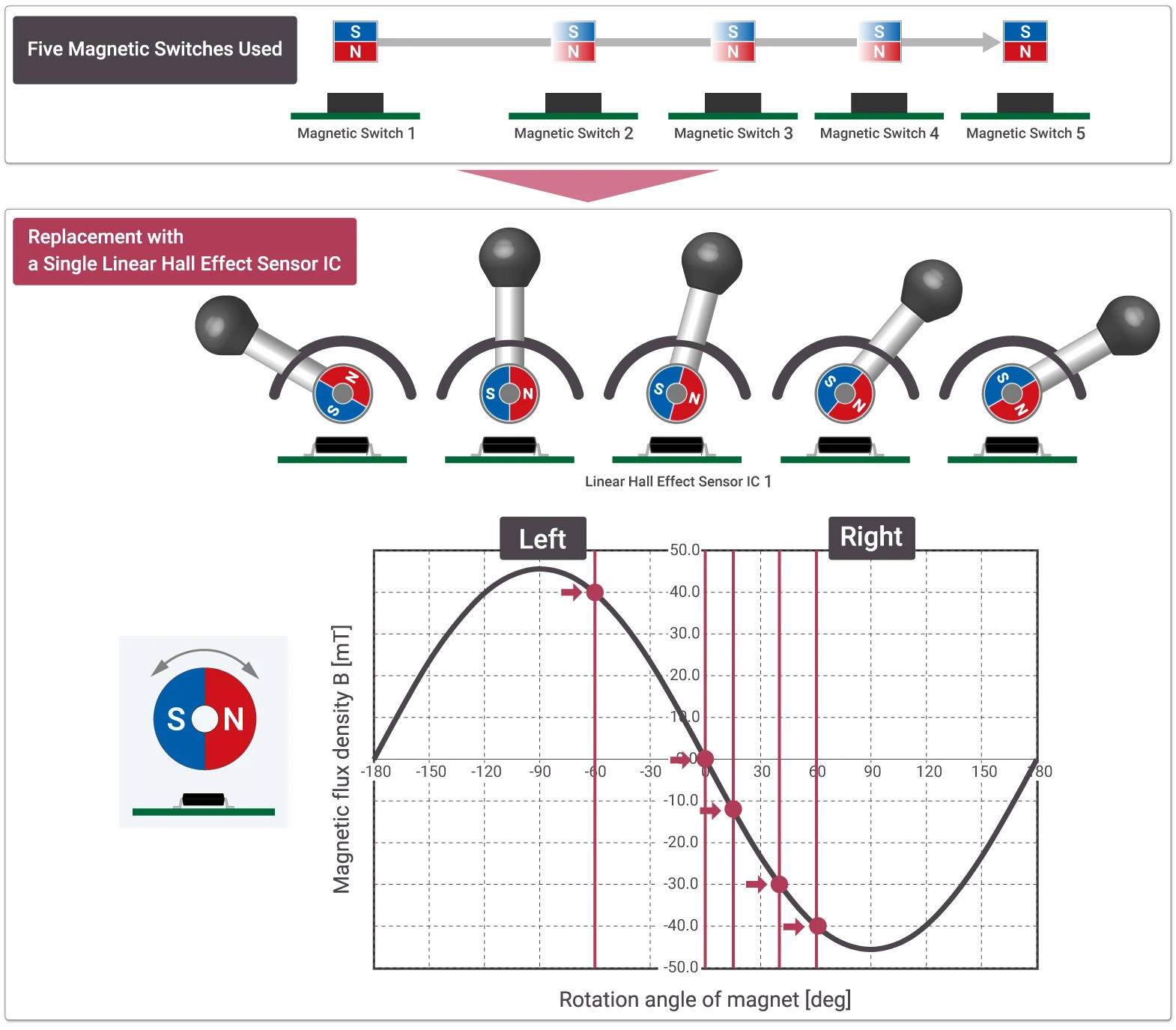
When Using Multiple Magnetic Switches (e.g., 5-Position)
A single linear Hall effect sensor IC can replace these switches and provide equivalent functionality.
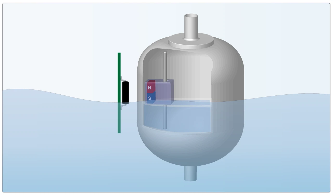
Sliding Position Detection (Float Sensor 1)
The linear Hall effect sensor IC detects changes in magnetic flux density from the magnet embedded in the float and outputs an analog voltage. By adjusting the magnetization direction and the size of the magnet, the system can accommodate various movement patterns. Because the peak voltage is high, this configuration enables high-sensitivity detection.
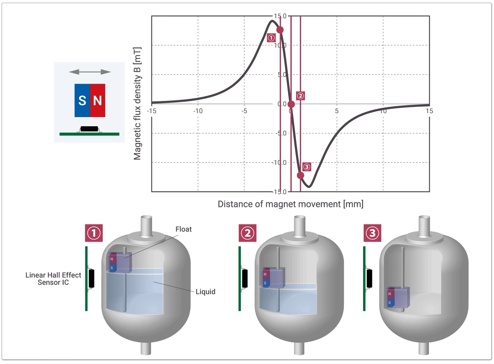
Rotational Position Detection (Float Sensor 2)
The float moves up and down according to the liquid level. The magnet embedded in the float is positioned so that it rotates around an axis as the float moves. The linear Hall effect sensor IC detects changes in magnetic flux density and outputs them as an analog voltage. By having the MCU monitor this voltage, position determination becomes possible. In this configuration, the resulting voltage change is more gradual than in the sliding position detection method described earlier.
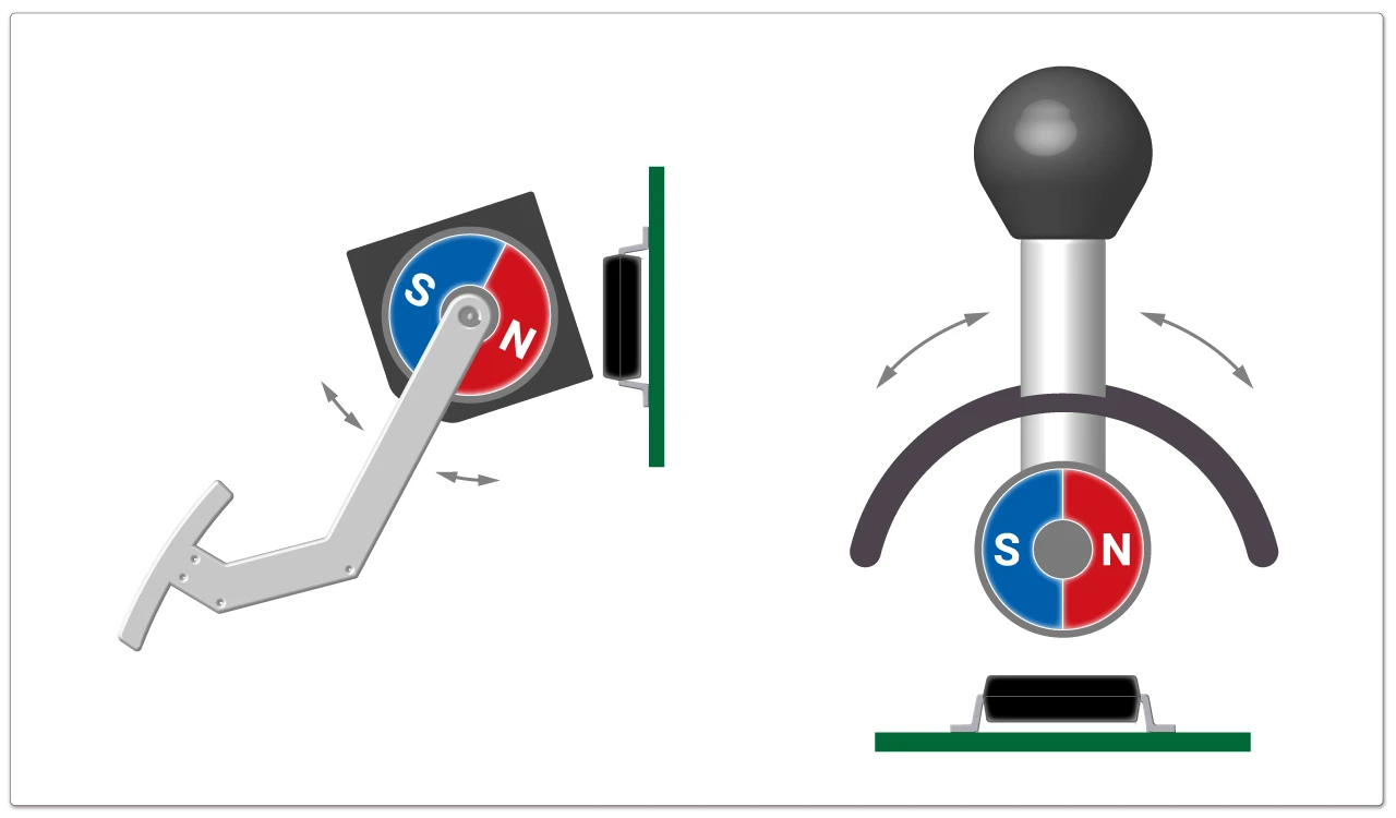
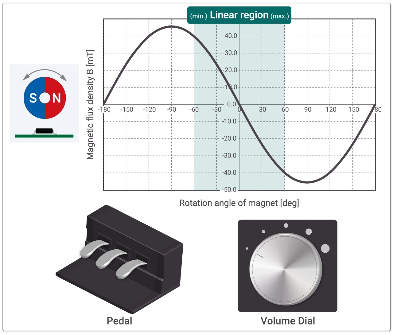
Rotational Position Detection (Pedal Depression Amount Detection, Volume Knob Rotation Detection)
The output changes according to the subtle amount of pedal depression. The magnet embedded inside the mechanism is positioned so that it rotates around an axis from the default position. The product is controlled based on the output corresponding to the detected magnetic flux density.
This functionality can be applied to rotational position detection applications, such as volume knobs, where the adjustment angle is typically between 0° and 120°. It is also possible to detect rotational positions up to approximately 0° to 180° in cases where output linearity is not required.
5. Need Help with Magnetic Design?
Introducing Our Magnetic Simulation Service
ABLIC offers a aagnetic simulation service that provides the ideal combination of magnets and our magnetic sensor ICs for customer systems.
By using this service, you can lower the hurdles associated with magnet design and check the operational behavior of both the magnet and the magnetic sensor ICs before prototyping. This upfront verification helps reduce the number of prototypes required, shortens the development period, and lowers development cost, contributing to the optimization of components for improved cost performance.
6. Try Out ABLIC's Linear Hall Effect Sensor ICs
| S-5611A Series | Programmable, fast-response | Buy Online (Price and Stock) |