Table of Contents
1. Electric Propeller Motors Demonstrate How Much More Efficient ZCL and Bipolar Hall Effect Latch ICs Are
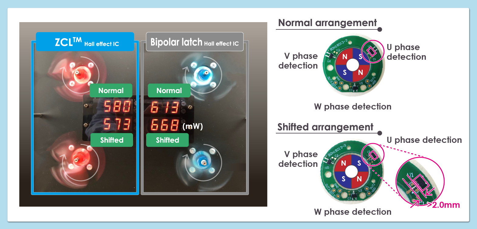
Energy efficiency of four different setups were tested: ZCL detection and bipolar Hall effect latch detection in both normal and shifted arrangement
These four electric propeller motors are powered by BLDC motors (brushless DC motors) using ABLIC Hall sensors. Each motor uses 3-phase control, so the ON / OFF timing of the U, V and W phases should ideally be exactly the same. However, there are slight deviations due to variations in sensor sensitivity and mounting conditions.
The electric propeller motors were developed to reproduce these conditions and demonstrate in numbers the advantages of ZCLTM Hall effect ICs. The Hall sensor board in the motors uses both Bipolar latch detection and ZCL detection sensors. The Hall effect sensors for the four motors were placed in a normal and in a shifted arrangement, respectively. Motor rpm for the four motors were adjusted so that a fair comparison of their energy efficiency could be made and the results could be seen on the display panel.
Normal arrangement
The position of and distance between the sensors and magnets are the same for the U, V, and W phases. This shows the Hall sensors mounted without misalignment and in a state where there is negligible variation in magnetic flux density.
Shifted arrangement
Only the position of the U-phase Hall sensor has been shifted upward by 2.0mm. This reproduces a Hall sensor that was misaligned during machine mounting or when there are variations in magnetic flux density. The magnetic flux density received by the U-phase Hall sensor is smaller than that of the V- and W-phase sensors, resulting in an imbalance.
2. Video Showing the Demonstration Results! The Energy Display Shows the Difference ZCL And Bipolar Hall Effect Latch ICs Make
ZCLTM Hall effect ICs are unaffected even when the Hall sensors are misaligned!
(Play time: 1 min. 36 sec.)
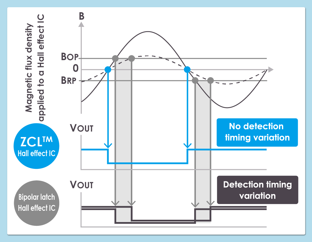
The bipolar Hall effect latch IC makes a detection only when the operating point (BOP) / release point (BRP) threshold level is reached.
If the magnetic flux density from the rotor changes for some reason, the output timing will shift as shown in the figure below. This is the reason for the lowered efficiency in a three-phase BLDC motor.
The electric propeller motors show that a motor using bipolar latch detection with the sensors placed in a shifted arrangement yields the highest power.
ZCLTM Hall effect ICs, on the other hand, operate at the zero-crossing point (where the magnetic flux density of the rotor is zero) and are not affected by changes in magnetic flux density. This characteristic means that ZCL detection and a shifted sensor arrangement in the electric propeller motors provides the same level of detection as the normal arrangement, which helps keep motor power low.