Table of Contents
1. Role of Hall Effect ICs in a BLDC Motor
In a BLDC motor (brushless DC motor), Hall effect ICs detect the position of the rotor to enable control of the proper timing when to pass current to the stator coils.
The following will describe the role of Hall effect ICs in a BLDC motor and the features required of a Hall effect IC.
2. BLDC Motor Control
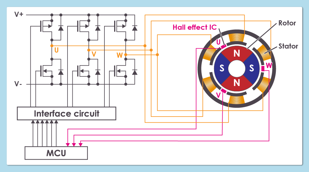
As shown in the figure, BLDC motor control detects the position of the rotating rotor and the motor control driver switches current to the coils to rotate the motor.
Detection of rotor position is an important part of this process.
Unless the rotor position is detected, the energization phase cannot be implemented at the precise timing when the stator and the rotor are in an appropriate flux relationship, resulting in less than adequate torque.
At worst, the motor will not rotate.
Hall effect ICs, which change their output voltage when they detect magnetic flux, are used for detecting rotor position.
3. Hall Effect IC Placement in BLDC Motor
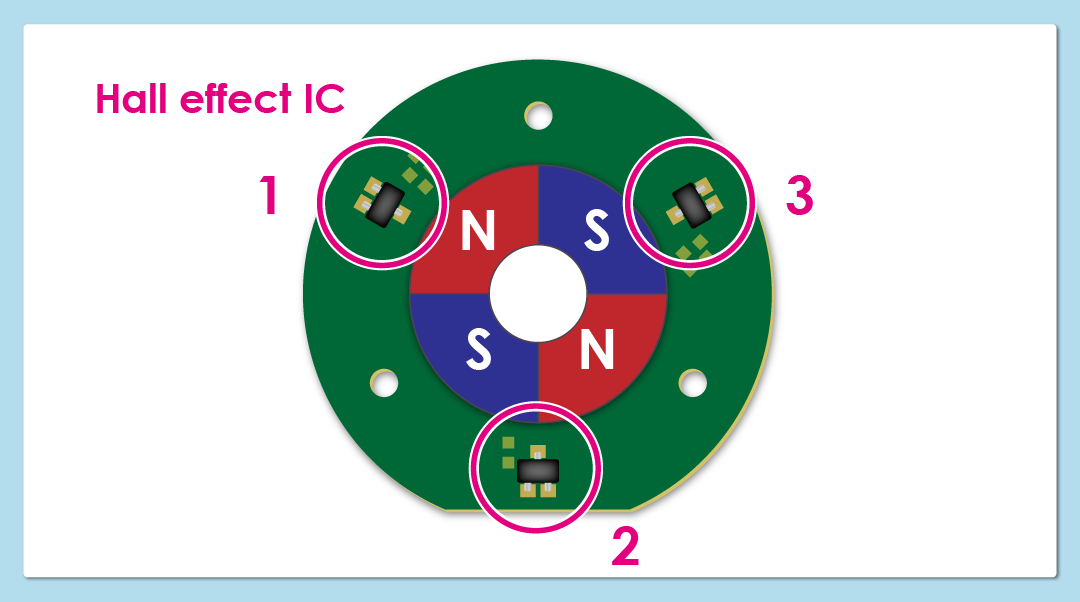
As shown in the figure, three Hall effect ICs are placed at an even distance apart on the 360° (electrical angle) circumference of the rotor.
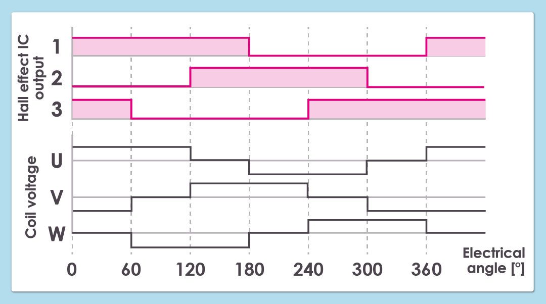
The combination of output signals from the three Hall effect ICs, which detect the magnetic field of the rotor, changes every 60° turn of the 360° circumference of the rotor.
This combination of signals changes the current that passes through the coil. In each phase (U, V, W), the rotor is energized for a 120° turn to generate an S-pole / N-pole.
The magnetic attraction and repulsion generated between the rotor and the coil cause the rotor to rotate.
Appropriate rotation control is thus achieved by controlling that power is passed from the driver circuit to the coils in accordance with the output timing of the Hall effect IC.
4. Hall Effect IC Detection Method
Hall effect ICs are used for detecting magnetic flux. They use the following three methods of detection.
| Unipolar detection: | The magnetic field at one pole (either N or S pole) is detected. |
|---|---|
| Omnipolar detection: | The magnetic field at both poles (N and S pole) is detected. |
| Bipolar latch: | The magnetic field at each pole (N and S pole) is detected alternately. |
In addition to these three methods, ABLIC also uses a proprietarily developed method of detection.
| ZCL detection: | The point (zero crossing point) where S pole changes to N or N pole to S is detected. |
|---|
As a BLDC motor rotates, the Hall effect IC is alternately exposed to magnetic fields from S-pole and N-pole.
Bipolar latch detection and ZCL detection Hall effect ICs are best suited for rotor position detection.
≫For details of the ZCLTM Hall effect IC, please refer to "What is the ZCL Hall effect IC?".
5. Features Required of a Hall Effect IC
A Hall effect IC must be able to quickly and accurately detect rotor position in rotation.
If the phase delay of the Hall effect IC output signal increases, the magnetic field generated in the coil causes the timing when the repulsive force is generated in the rotor to deviate from the optimal timing lowering the efficiency of the motor.
For that reason, a Hall effect IC for controlling detecting rotor position must be able to minimize the phase delay of the output signals it generates.
The following shows examples of causes of phase delays.
- Timing deviations caused by variations in operating point (BOP), release point (BRP) and magnetic flux density the Hall effect IC receives
- The timing deviation due to the output delay time of the Hall effect IC
For this reason, the following is required of a Hall effect IC.
- To accurately detect variations in the rotor magnetic field, variations in detection of operating point (BOP) and release point (BRP) must be minimal.
- To quickly return feedback of positional information, Hall effect IC output delay must be minimal.
≫For details on how to select a Hall effect IC,
please refer to "Hall Effect ICs That ABLIC Recommends for Each Motor Type."