Table of Contents
1. Why is Calibration Needed?
A BLDC motor (brushless DC motor) sometimes provides a post-assembly learning process (calibration process) in the motor manufacturing process to absorb design and manufacture variations and tolerances.
A BLDC motor is made up of numerous components.
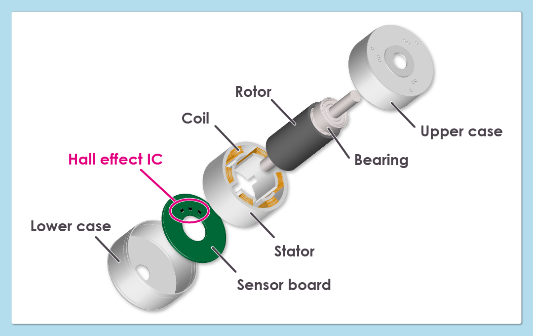
All these parts are manufactured with design and manufacture tolerances. As a result, the strength of rotor magnetic force, the magnetic sensitivity of Hall effect ICs and the rotor and Hall effect IC distance may not be uniform in all motors.
In addition, the motor produces heat during operation. Another problem is that when magnets, which are essential elements in a BLDC motor, become hot their magnetic force decreases. This also lowers the magnetic flux density that the Hall effect ICs receive to detect the rotation position of the rotor.
The calibration process is performed to optimize a motor so that the motor will realize its full potential with a minimum of variations. The calibration process performs the following adjustments to verify deviations of position detection caused by tolerances.
- Adjusts when current is to be passed to the coils and the Hall effect ICs are to output signals
- Adjusts the position of the sensor board to which the Hall effect ICs are mounted
- Adjusts advance angle and delay angle
- Performs temperature mapping to set the optimal current value for each table temperature
2. Methods to Streamline the Calibration Process
The calibration process is a labor-intensive process, but there are several ways to make it less time consuming.
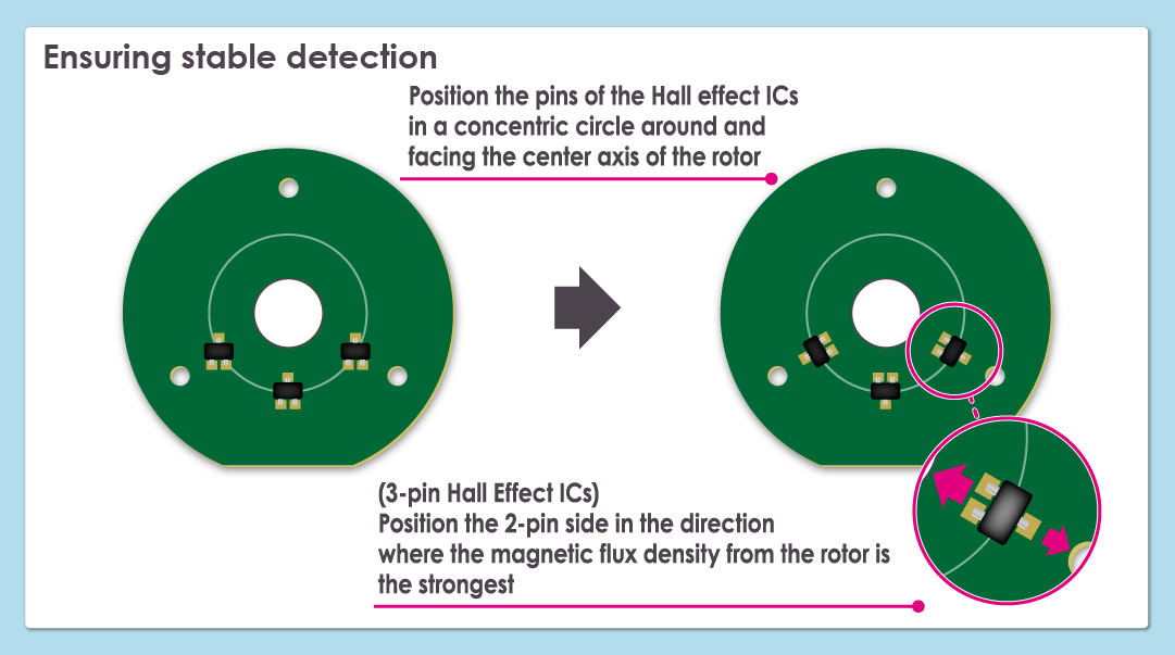
Mount the Hall effect ICs to the board in a circle around and concentric to the central axis of the rotor so that the pins of the Hall effect ICs face the center axis of the rotor
Like with other electronic components, Hall effect ICs are sometimes mounted in 90º increments of 0º, 90º, 180º and 270º on a sensor board, for ease of mounting. However, these are not ideal angles for Hall effect ICs for use in detecting rotor position.
The reason is that solder melting and resolidifying in the reflow process when electronic components are mounted to the board may cause the Hall effect ICs to move towards the edges of the board where the pins are. So if the Hall effect ICs were to be mounted in 90º increments, the sensor position of the Hall effect IC may deviate from the rotation angle of the motor it is supposed to detect.
Taking this misalignment into account, the pins of the three Hall sensor ICs on the board are placed facing the center axis of the rotor to more accurately detect the position of the rotor. This way of mounting reduces the effect of Hall effect IC misalignment caused by reflow.
Regular 3-pin Hall effect ICs will be closer to the 2-pin side, which has more pins. If the 2-pin side can be positioned in the direction where the magnetic flux density generated by the rotor is larger, more stable detection would be ensured.
Adjust the temperature characteristics of the rotor magnet with those of the Hall effect IC
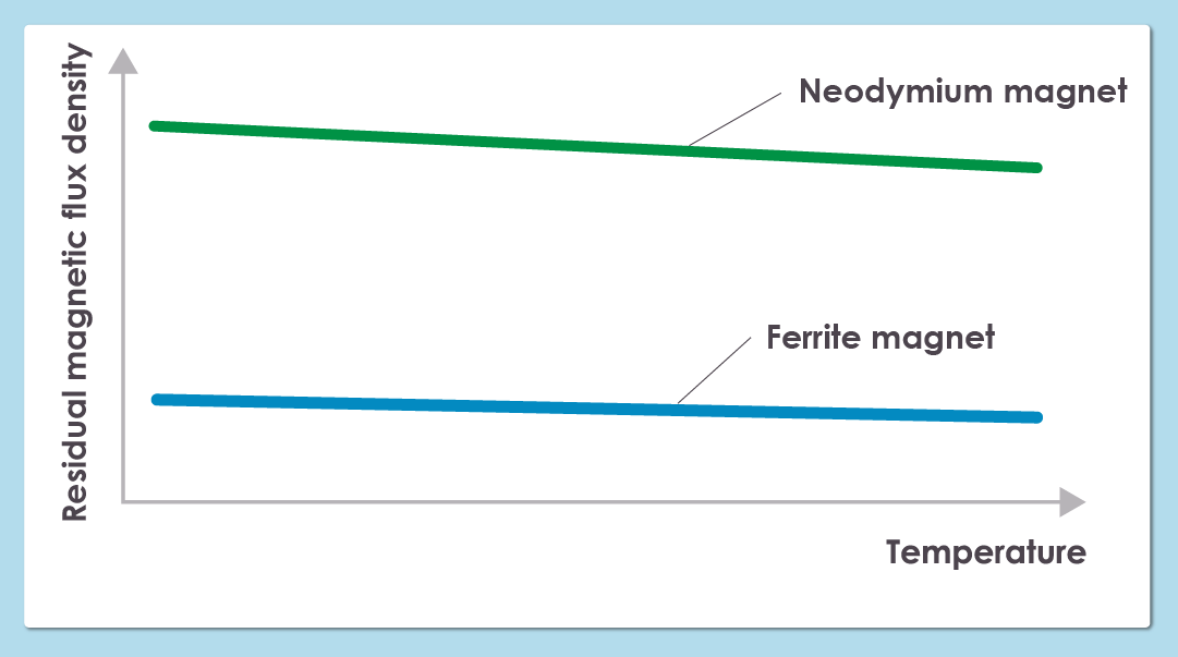
Ferrite magnets and neodymium magnets are generally used in rotors. To prevent deviations of position detection due to temperature, use Hall effect ICs adjusted to the temperature characteristics of ferrite and neodymium magnets.
Ferrite magnets normally have a temperature coefficient of -0.18%/ºC, while neodymium magnets have a temperature coefficient of -0.12%/ºC. Therefore, use Hall effect ICs*1 with temperature coefficients matching these temperature characteristics. However, note that the temperature coefficient value for most Hall effect ICs is a reference value and not a guaranteed value, so a certain degree of variation in production must be taken into account.
Try out our ZCLTM Hall effect ICs
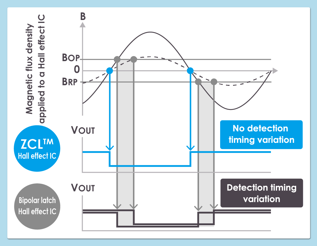
Use of ZCL Hall effect ICs, Hall effect ICs developed by ABLIC for BLDC motors, reduces the workload of motor calibration. Since the signal output by a ZCLTM Hall effect IC changes when magnetic flux density crosses 0mT, it is not affected by the change in magnetic characteristics due to temperature and can therefore change the signal at the same time.
Since the signal of a ZCLTM Hall effect IC outputs changes when 0mT is crossed regardless of the magnitude of magnetic flux density, there is no need to position the ICs in a concentric circle.
As indicated, there are many ways to reduce the workload of calibrating a BLDC motor, however, the use of ZCLTM Hall effect ICs is the simplest way to streamline calibration work.
ABLIC offers ZCLTM Hall effect ICs for automotive use, general use, industrial use and use in harsh environments.
We provide two different types of packages*2 of each of these applications.
*1: As of June 2022, ABLIC does not offer a lineup of Hall effect ICs that define a temperature coefficient.
*2: We provide the S-576Z R Series for use in harsh environments only in a TSOT-23-3S package.