Table of Contents
1. Three Factors Lowering BLDC Motor Efficiency
A Hall effect IC is required to quickly and accurately detect rotation position in rotation control of a BLDC motor (brushless DC motor).
Efficient rotation of the motor enables a substantial lowering of noise, heat and current consumption.
The following explains causes that lower BLDC motor efficiency in terms of Hall effect ICs.
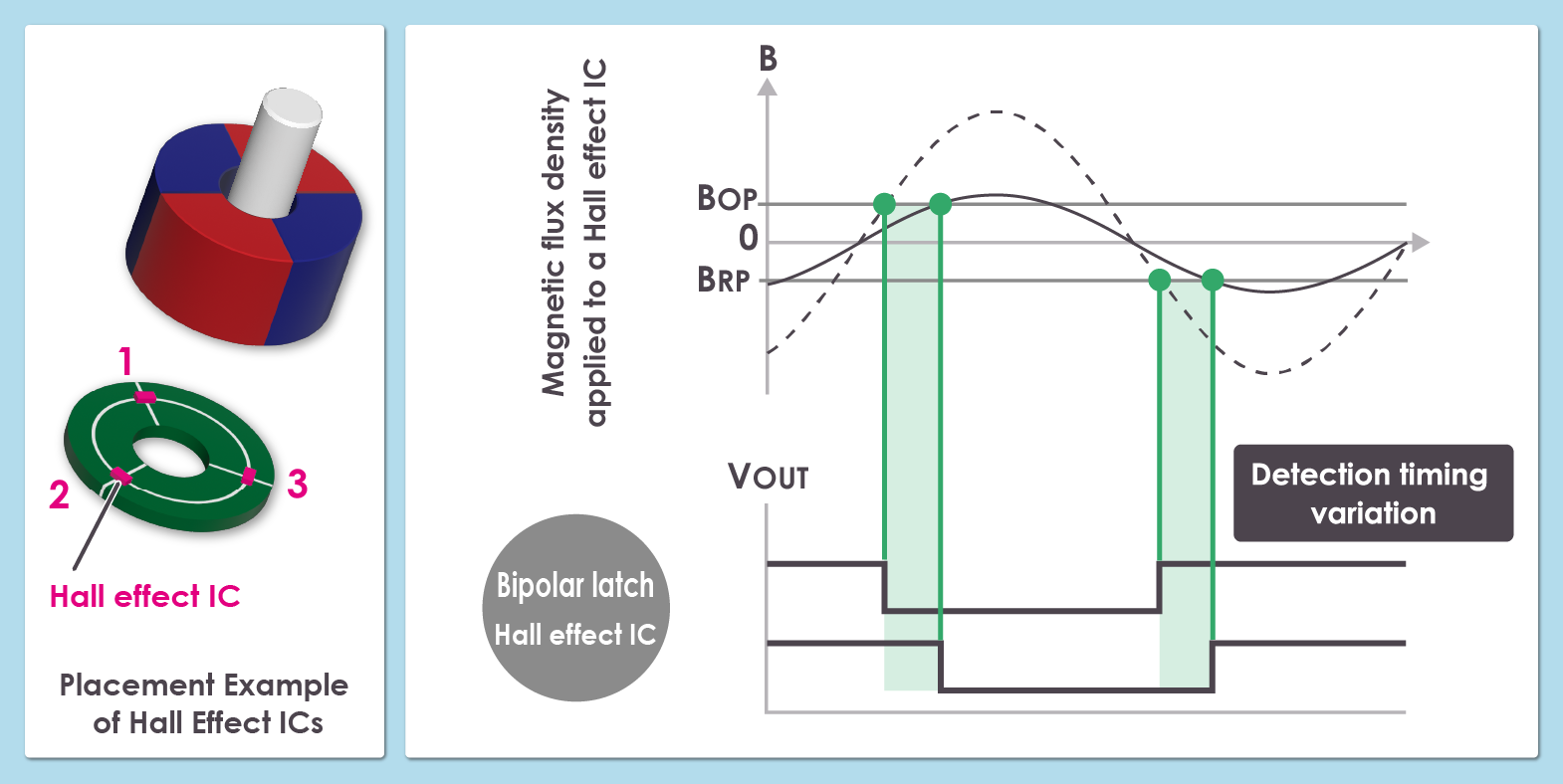
2. Hall Effect IC Placement
Three Hall effect ICs are used for detecting rotor position. Since the magnetic flux from the rotor must be uniformly detected, the Hall effect ICs must be placed at an equal distance from the magnet as shown in the figure.
Differences in the distance between the magnet and a Hall effect IC caused by mounting variations during manufacture lead to differences in the magnetic flux received by the Hall effect IC resulting in variations in the signals output by the Hall effect IC as shown in the figure.
Variations in the Hall effect IC output signals prevent appropriate timing of motor control lowering motor efficiency
3. Temperature Induced Variations
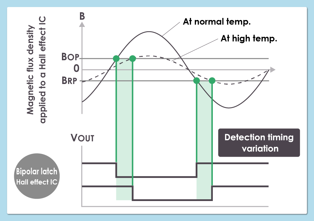
Normally, magnetic flux generated by a magnet increases and decreases with ambient temperature.
As a result, the magnetic flux received by the Hall effect ICs, changes causing the output signals to advance or delay.
Changes in ambient temperature change the motor control timing and deteriorate motor efficiency.
To prevent changes in the motor control timing, you can either create a complex motor control program that accounts for changes in magnetic flux caused by temperature or use Hall effect ICs whose variations in the detection of magnetic flux due to temperature changes are small.
4. Magnetic Sensitivity in Hall Effect ICs
The Hall elements and the signal processing circuits that make up a Hall effect IC are electronic components. Manufacturing variations in electronic components manufactured in large quantities will give rise to individual differences in electrical characteristics.
For example, variations in the sensitivity of Hall elements will cause variations in the operating point (BOP) and release point (BRP) at which the magnetic field is detected.
Such variations cause variations in the timing of position detection of the rotating rotor, which in turn reduces the efficiency of the motor.
Therefore, it is necessary to select a Hall effect IC with highly accurate magnetic sensitivity.
5. Drive System Differences
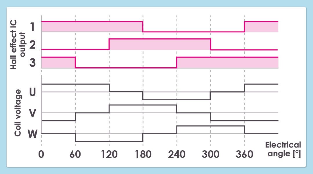
As shown in the figure, the square wave drive used in the 120 degree energization method detects the output signal of the Hall effect IC and switches the direction of the current flowing in the stator coils every 60 degree electrical angle.
The inductance component relative to the applied voltage of the square wave delays the flow of current in the coil.
This phase delay limits the efficiency that can be obtained.
However, compared to the sine wave drive described below, the square wave drive does not require a controller with high processing power. This drive method is often used in systems that require high-speed rotation at low cost.
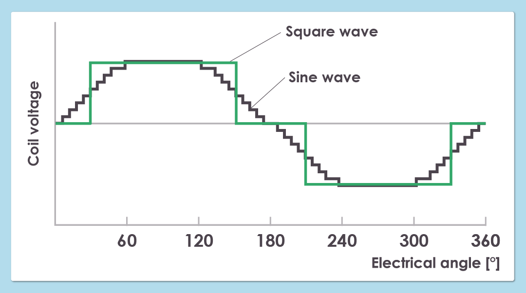
Sine wave drives are superior to square wave drives in terms of control accuracy, efficiency, and noise.
As shown in the figure, fine control of the applied voltage used in this drive method makes the motor current sinusoidal. This minute control of applied voltage reduces phase delay and improves the efficiency of the motor.
However, the required accuracy of rotor position detection demands use of a high-resolution encoder and a processing IC for converting Hall effect IC signals into complex program control, all of which results in higher costs.
6. Difference between SPM and IPM Rotor Magnets
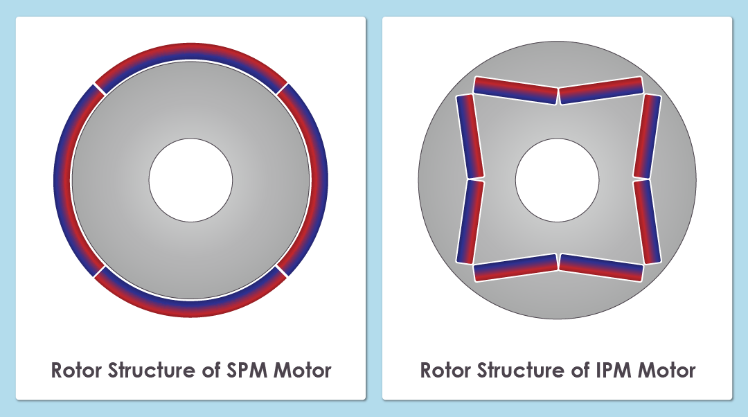
Depending on their structure, rotors using permanent magnets are either SPM (Surface Permanent Magnet) or IPM (Interior Permanent Magnet).
An SPM rotor has permanent magnets attached to the rotor surface and use only the magnetic torque generated by the magnets.
The exposed position of the magnets on the rotor surface makes high-speed rotation difficult in terms of mechanical strength, and eddy current loss demagnetizes the magnets reducing efficiency.
In contrast, the permanent magnets embedded in IPM rotors generate magnetic torque, and, thanks to magnetic resistance, also generate reluctance torque making this type of motor more efficient and yielding higher torque.
Since the magnets are inside the rotor in an IPM motor, the magnetic fields they generate are weaker and fluctuate. This results in an angular delay in detection by the Hall effect IC and reduces efficiency.
For this reason, additional sensor magnets often have to be installed to compensate. This makes it difficult to downsize the motor and increases costs.